Remote network monitoring system
A remote monitoring and monitoring system technology, applied in the transmission system, electrical components, etc., can solve the problems of limited number of extensions and limited transmission distance, etc., and achieve the effect of simple and easy system expansion
- Summary
- Abstract
- Description
- Claims
- Application Information
AI Technical Summary
Problems solved by technology
Method used
Image
Examples
Embodiment 1
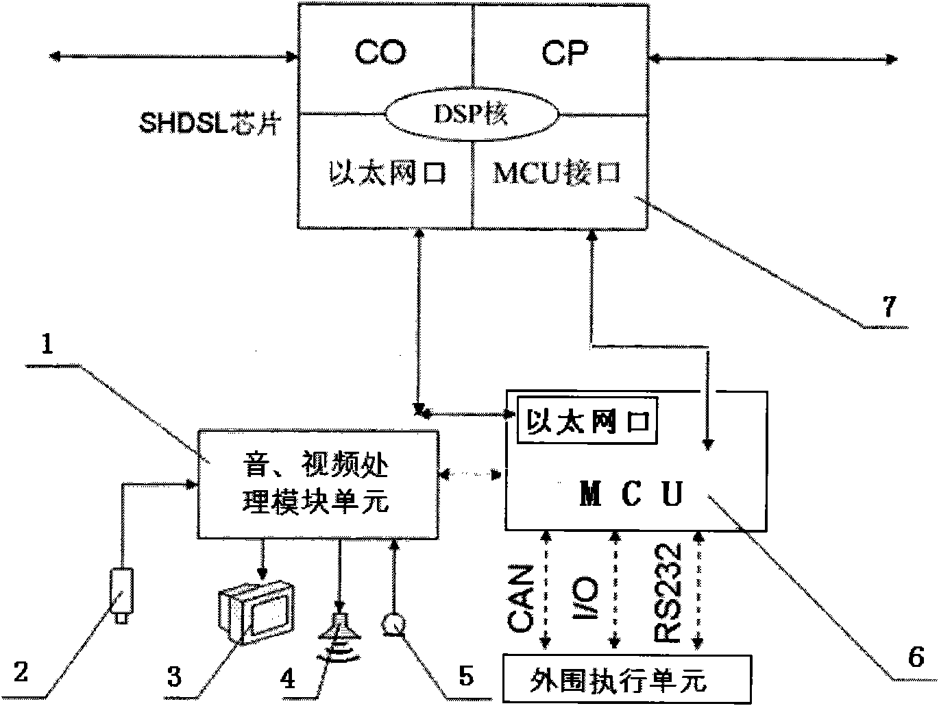
[0018] The remote monitoring system of the present invention can adopt a variety of network topologies. This embodiment introduces a remote monitoring system with a half-ring and a single daisy chain.
[0019] In the remote network monitoring system of the present invention, a monitoring host and a plurality of remote monitoring terminals are included, figure 2 It is a functional block diagram of a dual-port monitoring host and remote monitoring terminal; the monitoring host and each remote monitoring terminal are connected in series to form a single daisy chain; the monitoring host and the remote monitoring terminal include MCU and SHDSL chip; the MCU receives and sends through the SHDSL chip Data packet, when the SHDSL chip receives the data packet, the MCU judges whether the remote monitoring terminal is the destination terminal according to the destination address information in the data packet, if so, the MCU processes the data packet locally, otherwise, the MCU passes th...
Embodiment 2
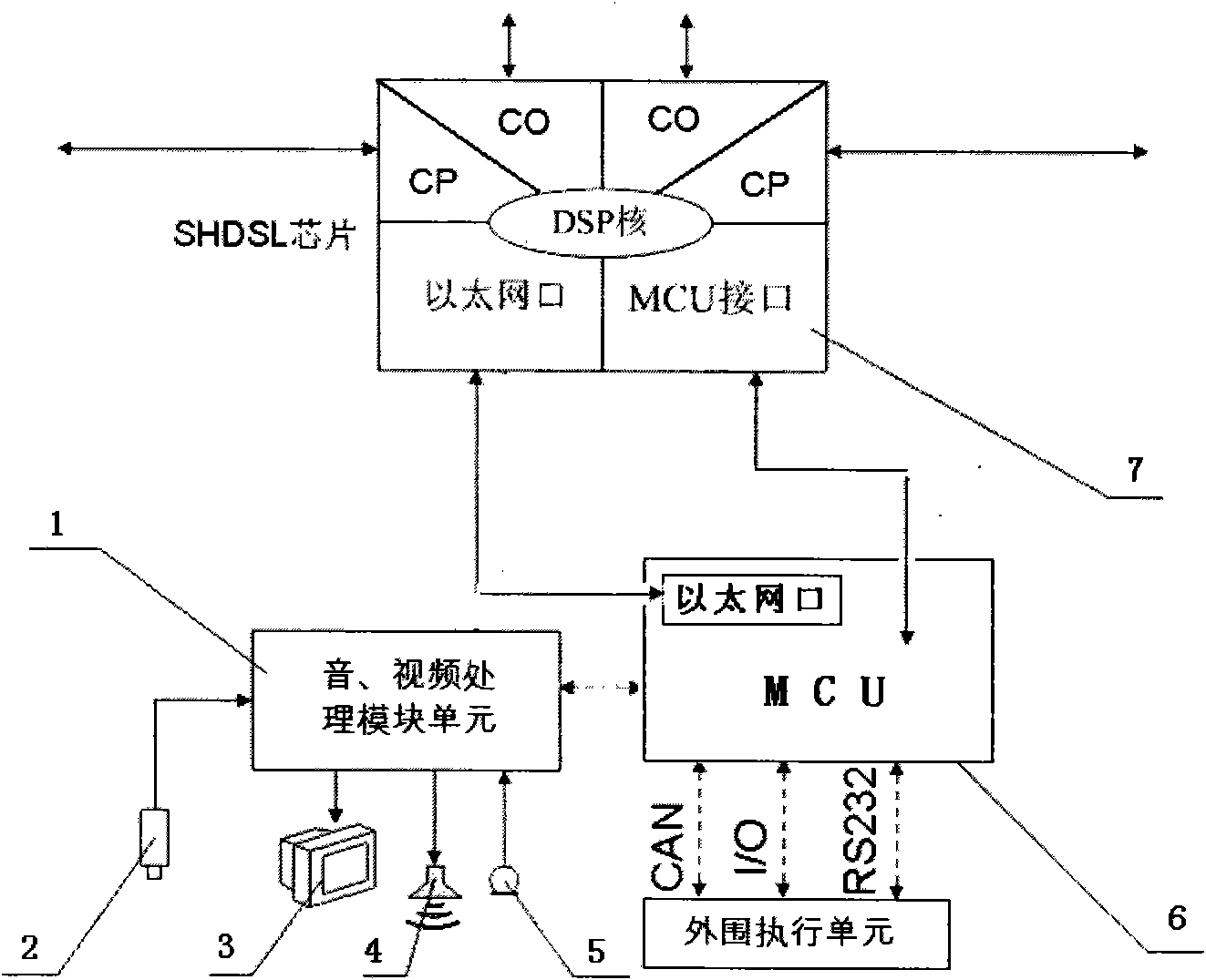
[0033] see image 3 The difference between this embodiment and Embodiment 1 is that the SHDSL chips of the monitoring host and the remote monitoring terminal in Embodiment 1 are configured as a pair of central office CO interfaces and terminal CP interfaces, while the SHDSL chips here are configured as two pairs of central office CO interface and terminal CP interface, the monitoring host and remote monitoring terminal under this configuration are called four-port monitoring host and remote monitoring terminal.
[0034] The advantage of this four-port configuration method is that the transmission bandwidth is doubled on the basis of the original two-port configuration, such as the bandwidth of 2M in the first embodiment, and the SHDSL chip is configured as four ports on the basis of the original system. Then the bandwidth becomes 4M. This configuration method of increasing bandwidth is simple and easy to implement, and is suitable for users with large bandwidth capacity requir...
Embodiment 3
[0037] This embodiment provides several topological connection modes between the monitoring host and each remote monitoring terminal.
[0038] see Figure 4 and Figure 5 , are two kinds of network topologies. Figure 4 It is a network topology diagram of a half-ring single daisy chain, Figure 5 It is a network topology diagram of a full-ring single daisy chain remote monitoring system.
[0039] We have known that the SHDSL chip includes the CO interface of the central office and the CP interface of the terminal by embodiment one, and the CO (CP) interface of the central office and the terminal CP (CO) interface of another SHDSL chip are connected in pairs, and the monitoring host computer and each remote The monitoring terminals are connected in series through the above-mentioned paired connections between the CO and CP interfaces.
[0040] Due to the difference in logarithm of the CO and CP interfaces, the series connection between the monitoring host and each remote mo...
PUM
 Abstract
Description
Claims
Application Information
 - R&D
- Intellectual Property
- Life Sciences
- Materials
- Tech Scout
- Unparalleled Data Quality
- Higher Quality Content
- 60% Fewer Hallucinations
Browse by: Latest US Patents, China's latest patents, Technical Efficacy Thesaurus, Application Domain, Technology Topic, Popular Technical Reports.
© 2025 PatSnap. All rights reserved.Legal|Privacy policy|Modern Slavery Act Transparency Statement|Sitemap|About US| Contact US: help@patsnap.com


