

Heat exchanger comprising a fractal pipe structure
Patent Information
- Authority / Receiving Office
- CN · China
- Current Assignee / Owner
- BSH BOSCH & SIEMENS HAUSGERAETE GMBH
- Publication Date
- 2010-12-29
- Estimated Expiration
- Not applicable · inactive patent
Smart Images
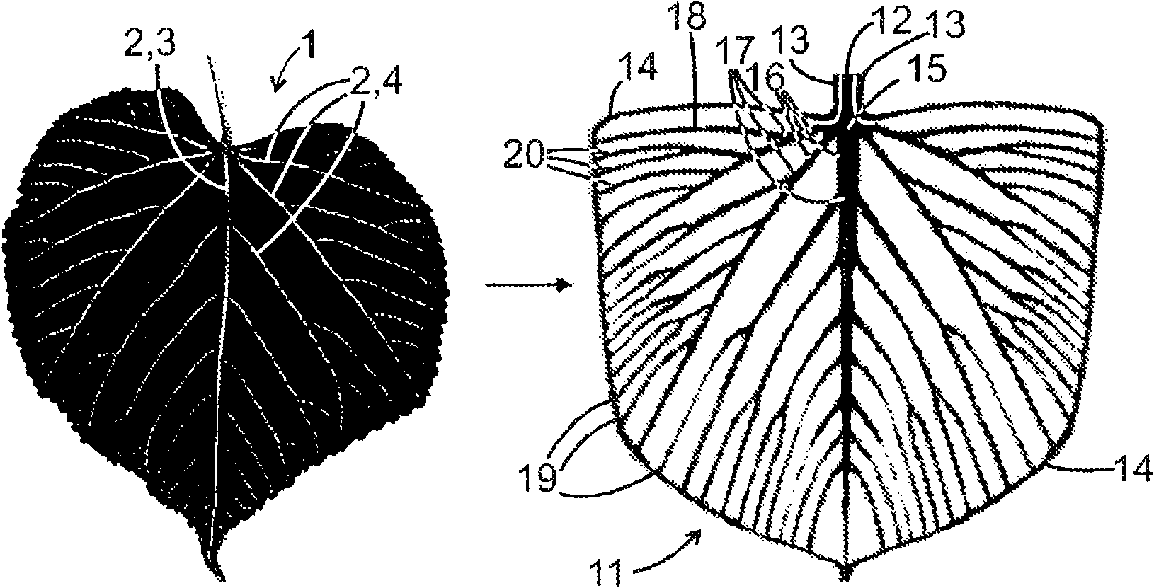
Figure 1 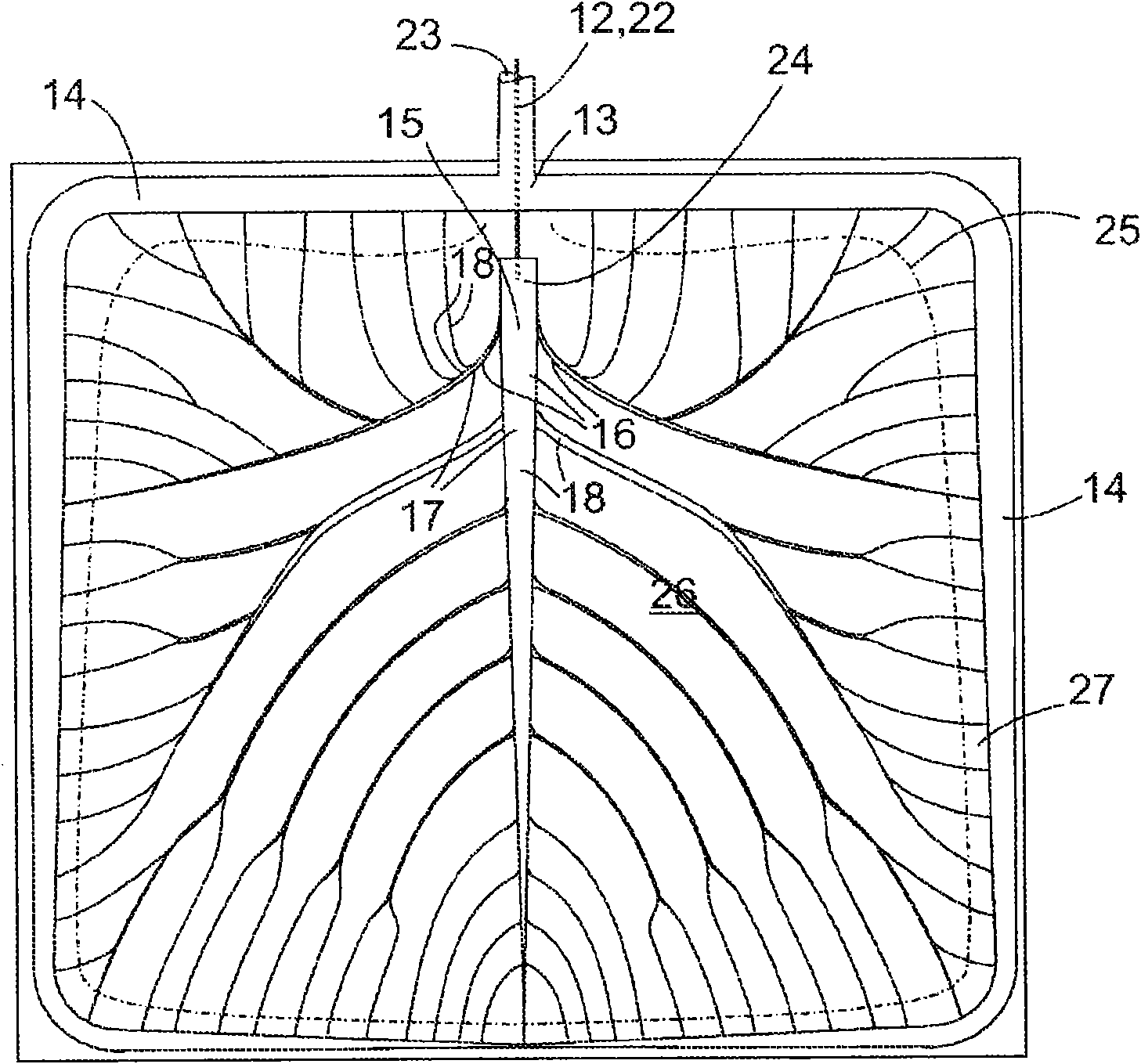
Figure 2 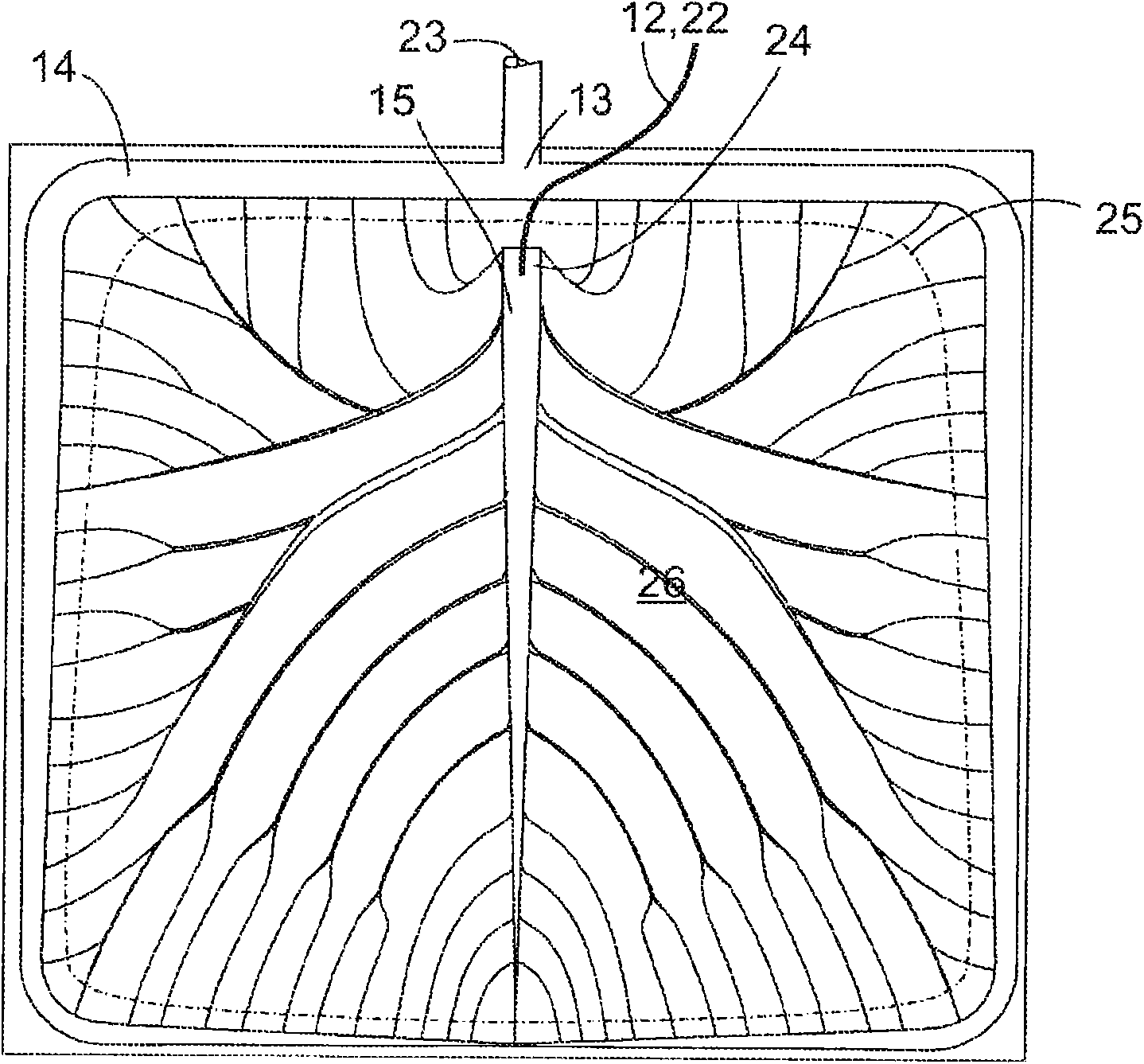
Figure 3
Abstract
Description
technical field
[0001] The invention relates to a heat exchanger, especially a heat exchanger suitable for use as an evaporator in a refrigeration appliance. Existing heat exchangers with unbranched tube structures generally comprise a base plate on which a continuous tube extends serpentinely from an input connection to an output connection. By means of the meandering delicate extension, the temperature change associated with the supply of the heat transfer fluid can be spread over the entire surface of the substrate in a short time. However, it has the disadvantage that the large length of the individual tubes causes a sudden drop in the pressure of the heat transfer fluid in the heat exchanger, thus requiring a high driving power to circulate the heat transfer fluid. The serpentine route enables heat exchange between adjacently extended upstream and downstream sections of the tube, which reduces the efficiency of the heat exchanger. Background technique
[0002] A heat ...