T-shaped joint welding method

A welding method and welding current technology, applied in welding equipment, arc welding equipment, manufacturing tools, etc., can solve problems such as box structure damage, achieve the effect of improving welding quality and reducing welding defects

Inactive Publication Date: 2011-01-05
龙工(上海)挖掘机制造有限公司
View PDF0 Cites 14 Cited by
  • Summary
  • Abstract
  • Description
  • Claims
  • Application Information

AI Technical Summary

Problems solved by technology

The boom and arm are subjected to alternating stress during use. Welding defects, small cracks in the weld and low-strength joints in the local area of ​​the weld are gradually destroyed and developed under the action of alternating stress, starting from the microscopic Small cracks develop into weld cracks that can be observed, and finally cause serious damage to the entire box structure

Method used


Image

  • T-shaped joint welding method
  • T-shaped joint welding method
  • T-shaped joint welding method

Examples


Embodiment Construction

[0025] The present invention will be further described below in conjunction with the accompanying drawings and embodiments.

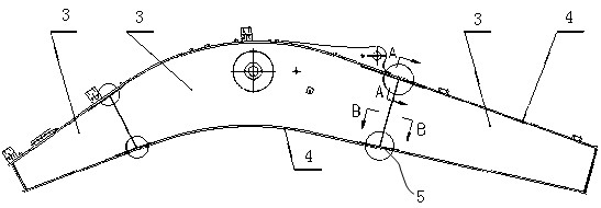
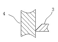
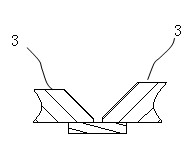
[0026] Figure 5 It is the initial schematic diagram of the welding seam at the T-shaped joint of the present invention; Figure 6 It is a schematic diagram of a T-shaped weld of the present invention.

[0027] See Figure 5 and Figure 6 , the T-shaped joint welding method provided by the invention comprises the steps:

[0028] a) Backing welding of side plate groove welds; welding current 260-280A, arc voltage 25-29 V; weld thickness less than 5mm, arc starting position of the weld is 20mm from the top of the side plate groove weld. At the seam, the arc closing position of the welding seam is at the longitudinal welding seam 20mm away from the top of the side plate groove weld, that is, the arc starting and arc closing are completed at one time, and the distance between the arc starting position and arc closing position and the main weld is 8 L1 ...


PUM

PropertyMeasurementUnit
lengthaaaaaaaaaa

Abstract

The invention discloses a T-shaped joint welding method comprising the following steps of: (a) carrying out backing welding on the main weld of the groove of a side plate, wherein the arc starting position and the arc ending position of the weld are at the longitudinal weld position which is at least 20mm away from the top end of the main weld of the groove of the side plate; (b) cleaning interlayer welding slag, and carrying out intermediate layer welding and cosmetic welding on the main weld of the groove of the side plate, wherein the arc starting position and the arc ending position of the weld are the same as the backing welding in the step (a); (c) removing the arc starting and arc ending welds in the longitudinal weld by using carbon arc gouging at both ends of the main weld of the groove of the side plate, and polishing clean an angular grinding wheel for removing surfaces so as to make the groove ground out; and (d) carrying out the backing welding and the cosmetic welding on the longitudinal angular weld. The T-shaped joint welding method effectively reduces the welding defect of the weld at the T-shaped junction and improves the welding quality of a structure through controlling the arc staring position and the arc ending position of the main weld of the groove of the side plate and removing and polishing the arc starting and arc ending welds.

Description

technical field [0001] The invention relates to a welding method, in particular to a T-shaped joint welding method. Background technique [0002] The most important welded structural parts of the excavator are the boom and the arm, both of which are box-shaped welded structures, and the multiple welds on the side plate and the cover plate form a T-shaped cross joint. Such as figure 1 As shown, a plurality of boom side plates 3 and two cover plates 4 are welded into a box-shaped structure, and a T-shaped joint 5 is formed between the side plates and between the side plates and the cover plates. There is a groove at the joint between the side plate 3 and the cover plate 4, such as figure 2 Shown; the groove form of the joint of side plate 3 is as follows image 3 shown. The welding seam at the above-mentioned groove is the main welding seam of the boom, and its welding quality is related to the strength level and service life of the boom arm parts. [0003] The existing...

Claims


Application Information

Patent Timeline
Patent Type & Authority Applications(China)
IPC IPC(8): B23K9/00B23K9/02B23K9/013B23K9/235B23K9/095
Inventor 陈国良
Owner 龙工(上海)挖掘机制造有限公司
Why Eureka
Try Eureka