Method and device for producing thick-walled plastic components, in particular optical components

A technology for plastic parts and plastics, applied in the field of manufacturing plastic parts, can solve the problems of neglect and increased material consumption, and achieve high quality and reduce separation marks.

Inactive Publication Date: 2011-01-05
BAYER MATERIALSCIENCE AG
View PDF4 Cites 9 Cited by
  • Summary
  • Abstract
  • Description
  • Claims
  • Application Information

AI Technical Summary

Problems solved by technology

Also, in the case of optics, due to the transparent material, there is often a lot of area that could theoretically be used to place gates for aesthetic reasons that is often not considered
In addition, thick runners generally incur additional costs due to reworking of gate marks (separation marks)
Additionally, relatively large or thick sprues cause increased material consumption

Method used


Image

  • Method and device for producing thick-walled plastic components, in particular optical components
  • Method and device for producing thick-walled plastic components, in particular optical components
  • Method and device for producing thick-walled plastic components, in particular optical components

Examples


Embodiment Construction

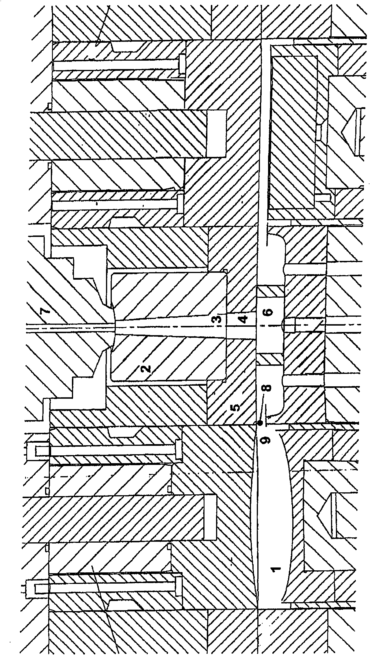
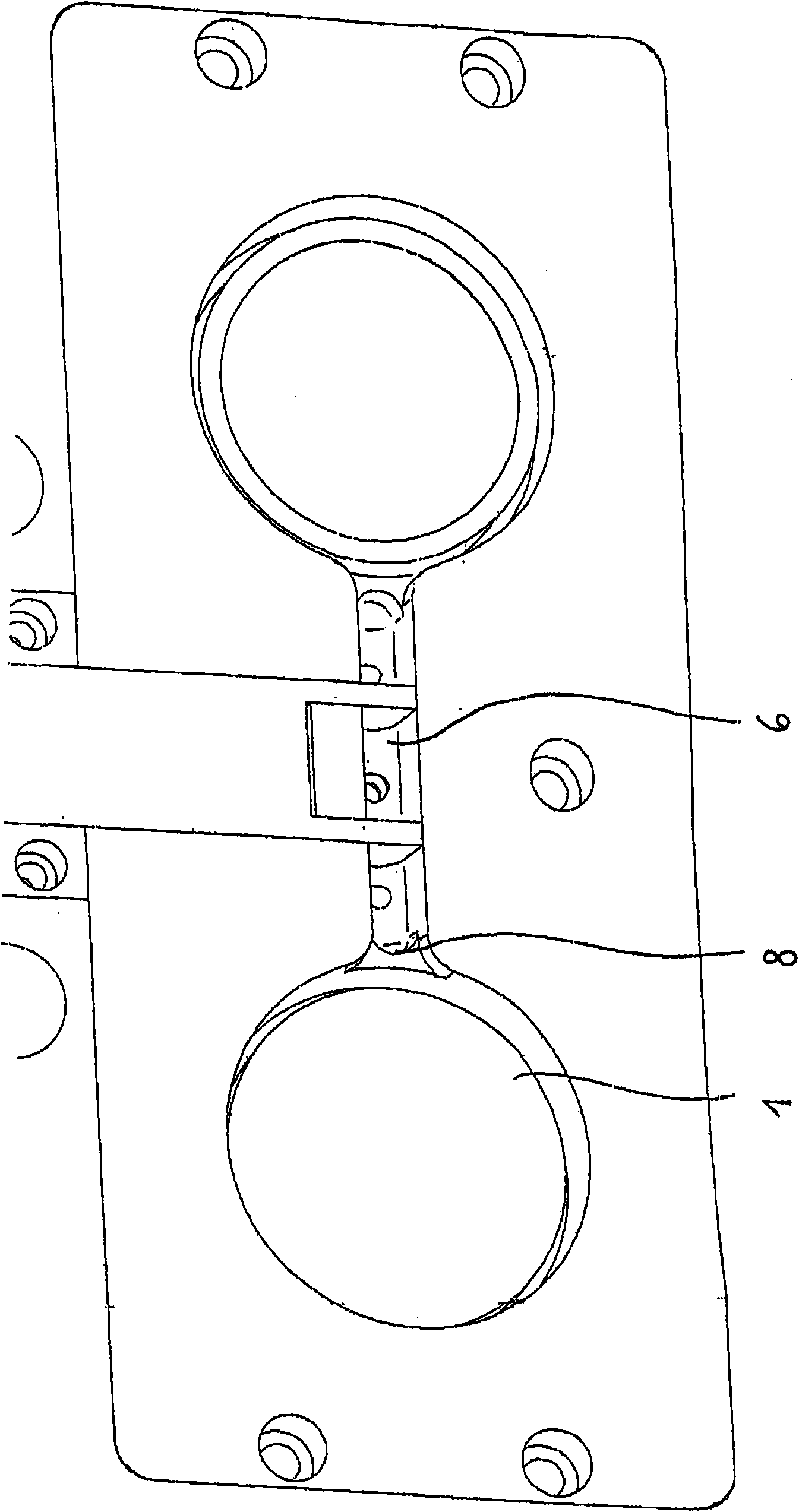
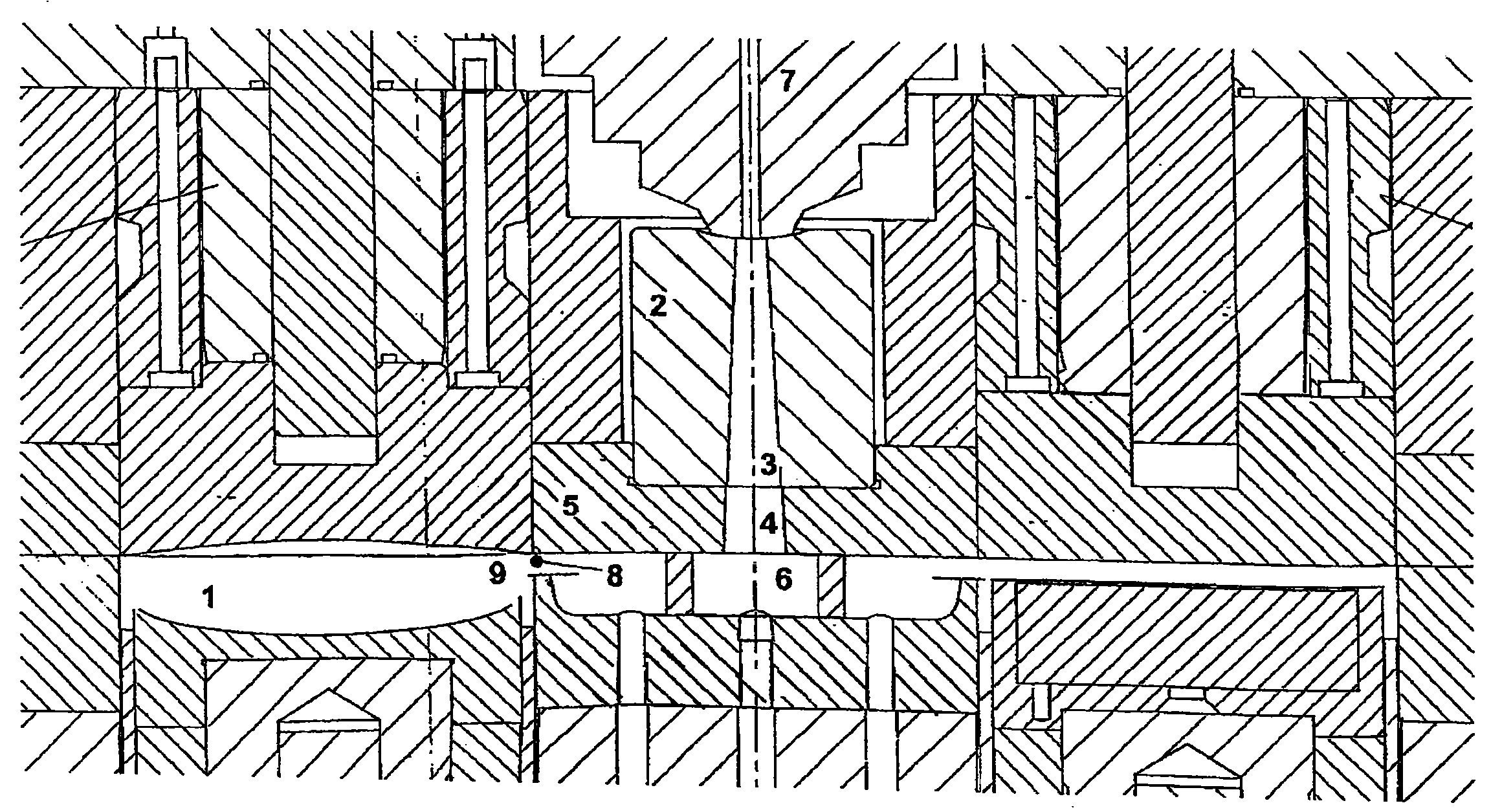
[0023] The injection-molding tool described in the figures is used for the manufacture of transparent parts, especially optical lenses, from synthetic materials. The injection-molding tool is composed of several parts defining a cavity 1 shaping the part to be manufactured.

[0024] In the exemplary embodiment shown, the injection-molding tool comprises a sprue bushing 2 with a conical channel 3 . This channel 3 leads to a further, likewise conical, channel part 4 , which passes through the plate-shaped tool part 5 and leads to a flow channel 6 . Through the runner 6, the plastic melt passing from the nozzle 7 of the injection-molding machine with the injection-molding screw or other feeding means to the sprue bushing is introduced into the cavity 1 . For the runner 6, cold runners are preferably considered.

[0025] The gate 8 for the melt is arranged at the edge of the cavity 1 such that the gate 8 is located at the periphery of the disc-shaped plastic part, thus on the na...


PUM


Abstract

The invention relates to a process for producing plastic components, in particular optical lenses or optical light-guides, wherein plastic melt is injected via a sprue (3, 4, 6, 8) into a cavity (1) of a moulding tool shaping the component and additional plastic melt is after-pressed into the cavity (1) for the purpose of compensating a volume contraction of the injected plastic melt due to cooling. The process is characterised in that the plastic melt located in the sprue (3, 4, 6, 8) is kept flowable by means of energy introduced in the region of the sprue until such time as the molten core of the plastic component has solidified in the course of the after-pressing of plastic melt for the purpose of compensating the volume contraction due to cooling (holding-pressure). The invention further relates to an apparatus for implementing the process.

Description

technical field [0001] The present invention relates to a method of manufacturing a plastic part - in particular an optical lens, optical light guide or other optical part - in which a plastic melt is injected through a sprue into a cavity of a molding tool which shapes said part, and additionally The plastic melt is pressed into the cavity to compensate for the volume shrinkage of the injected plastic melt due to cooling (holding pressure). To this end, gates can be provided on narrow side walls of the component. The invention further relates to an apparatus for injection molding or injection-compression molding of said plastic parts with a chamber and supply means for shaping said plastic parts to be produced, for example injection molding A screw for feeding plastic melt into the cavity via a sprue. Background technique [0002] Especially in the case of injection molding of thick-walled plastic parts, such as optical parts, where very strict requirements are placed on ...

Claims


Application Information

Patent Timeline
Patent Type & Authority Applications(China)
IPC IPC(8): B29C45/73B29C45/27B29L11/00
CPCB29C45/2756B29C45/57B29C45/2737B29C45/568B29K2101/12B29C45/2708
Inventor R·普罗特C·克林肯伯格
Owner BAYER MATERIALSCIENCE AG
Why Eureka
Try Eureka