
Airbag wiper in automobile cleaning equipment

A technology for cleaning equipment and airbags, applied in the direction of vehicle external cleaning devices, etc., can solve the problems of car loss, increased cleaning costs, and insufficient operating space, and achieve the effect of improving decontamination efficiency and easy removal

Active Publication Date: 2011-01-05
JIANGSU XIHU SPECIAL STEEL
View PDF5 Cites 4 Cited by
  • Summary
  • Abstract
  • Description
  • Claims
  • Application Information

AI Technical Summary

Problems solved by technology

Except for the flexibility of the brush head, the entire cleaning head is almost rigid. If the operating space reserved during cleaning is not large enough, the moving parts of the cleaning head will collide with the car being cleaned, which may cause damage to the car being cleaned. , resulting in an increase in cleaning costs

Method used


Image

  • Airbag wiper in automobile cleaning equipment
  • Airbag wiper in automobile cleaning equipment
  • Airbag wiper in automobile cleaning equipment

Examples


Embodiment 1

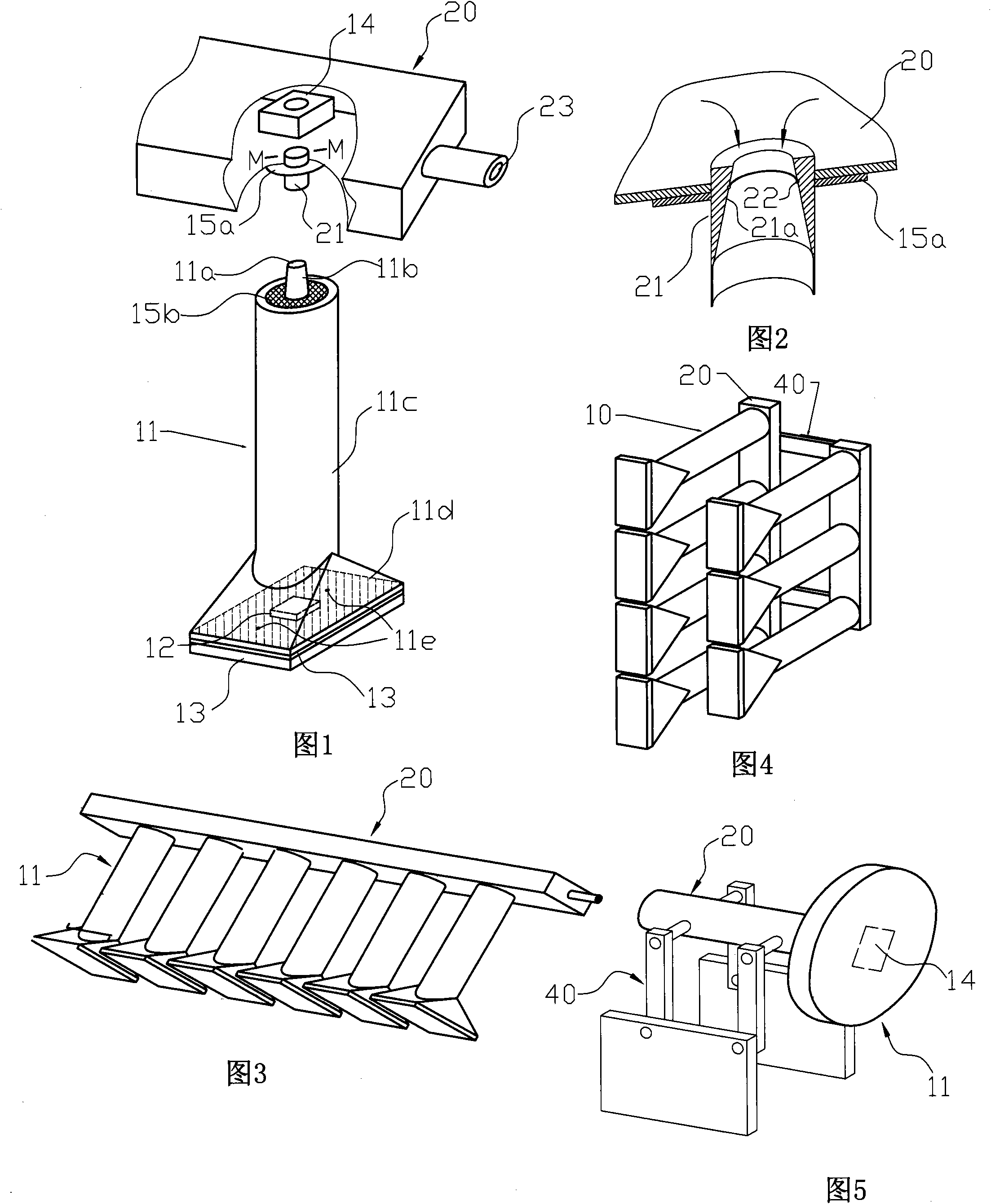
[0025] control figure 1 The airbag wiper 10 mainly consists of an airbag 11, a pneumatic vibrator 12 and a wiping material 13, and the airbag wiper 10 is connected to a square trachea 20 with high-pressure gas. The air bag is a combination of a cylindrical air bag 11c and a quadrangular pyramidal air bag 11d. The air pipe 20 is provided with a corresponding air outlet pipe 21 , and the air inlet of the air outlet pipe 21 is connected with a solenoid valve 14 to control the gas entering the airbag wiper 10 . The inner peripheral surface of the air outlet pipe 21 is provided with an inner conical surface 21a with the same taper as the upper outer conical surface of the inlet pipe 11a. The inner conical surface 21a is also provided with a sealing ring groove, and a sealing ring 22 is placed in the groove. The airbag wiper 10 is plugged in the air outlet pipe 21 of the trachea 20 through the air inlet pipe 11a on it to realize the communication between the two, and utilize the mu...

Embodiment 2

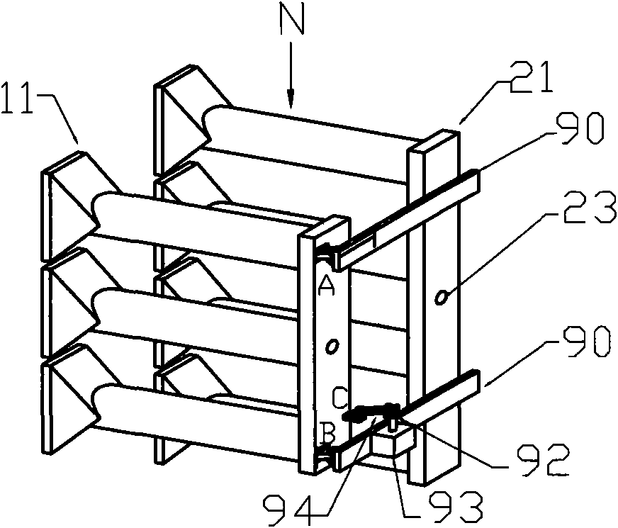
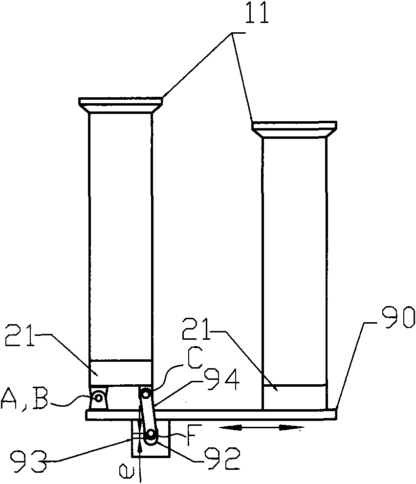
[0032] The wiping movement of the airbag to the car body can also be produced by the swing mechanism, such as Image 6 . Pneumatic vibrators are not placed in the airbag 11 like this. The airbag wiper is mainly composed of a trachea, an airbag, a wiping material, a rotating cylinder, a bracket, a connecting rod and an eccentric block. Wherein the rotary cylinder 93 is installed on the support 90, the communication form of the air pipe 20 and the air bag 11 and the structural form of the air bag 11 are the same as the above-mentioned embodiment, and the required swing of the air bag to wipe the vehicle body is composed of the air pipe 20, the rotary air cylinder 93, the support. 90, the connecting rod swing mechanism that connecting rod 94 and eccentric block 92 form. The bracket 90 is fixed on the car cleaning equipment, two points A and B at a certain distance on the trachea 21 are respectively hinged with the bracket 90, and the point C on the trachea 20 which is not in a ...


PUM


Abstract

The invention relates to an airbag wiper in automobile cleaning equipment. The airbag wiper comprises an air pipe, airbags, a pneumatic vibrator and a wiping material, wherein the air pipe is connected with an air source which is larger than atmospheric pressure; at least one airbag is communicated with the air pipe; and the wiping material is adhered on the outer lateral surface corresponding to the wiping part of the airbag, and the pneumatic vibrator is arranged inside the airbag. In the airbag wiper, the pneumatic vibrator enables the airbag to vibrate, and the airbag is used to clean the automobile flexibly, which is equivalent to manual wiping by cleaning cloth, and the cleaned body is protected from damage; And due to the soft airbag, the airbag can be closely contacted with a cleaning material easily during cleaning, so stains can be easily removed, and the cleaning efficiency can be improved. Therefore, the airbag wiper has the advantages of no damage to the automobile and water conservation, can be arranged in small space, and is particularly suitable for mechanical automobile cleaning in northern, loess plateau and other water-deficient area areas.

Description

technical field [0001] The invention relates to a car cleaning device, in particular to an airbag wiper in the car cleaning device. Background technique [0002] At present, the cleaning head in the car cleaning equipment on the market is a brush head driven by a motor, and the car is cleaned by the rotation of the brush head. Except for the flexibility of the brush head, the entire cleaning head is almost rigid. If the operating space reserved during cleaning is not large enough, the moving parts of the cleaning head will collide with the car being cleaned, which may cause damage to the car being cleaned. , resulting in an increase in cleaning costs. Contents of the invention [0003] The purpose of the present invention is to design a kind of car washing equipment that does not damage the car and has low cost by simulating the principle of car washing, and it is realized by the following technical solutions: [0004] The airbag wiping includes a trachea, an airbag, a p...

Claims


Application Information

Patent Timeline
Patent Type & Authority Applications(China)
IPC IPC(8): B60S3/04
Inventor 张山峰
Owner JIANGSU XIHU SPECIAL STEEL
Learn More