
Electroplating cathode conductive device

A cathode conductive and pressing device technology, applied in the direction of the electrode, etc., can solve the problems of poor contact between the rotating shaft and the brush, affect the quality of the plate roller, and uneven coating, so as to avoid poor contact, ensure service life, and uniform coating.

Active Publication Date: 2011-01-05
JIANGSU HUYUN PLATE MAKING
View PDF6 Cites 4 Cited by
  • Summary
  • Abstract
  • Description
  • Claims
  • Application Information

AI Technical Summary

Problems solved by technology

For the above two conductive devices, since the brush is fixed, it is easy to wear the rotating shaft, and the contact between the rotating shaft and the brush is poor, resulting in uneven coating, rough surface, and poor bonding force, which affects the quality of the plate roller.

Method used


Image

  • Electroplating cathode conductive device
  • Electroplating cathode conductive device

Examples


Embodiment 1

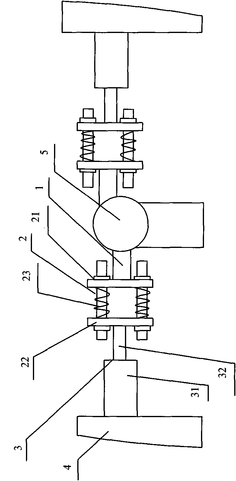
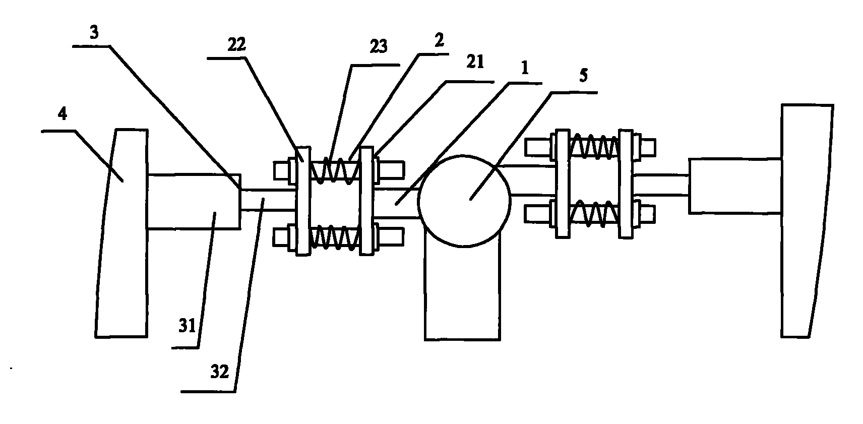
[0018] In order to further improve the conductive device, in this embodiment, the compression device 3 is used as an example for illustration. The present invention includes a brush 1, a connecting device 2, and a compression device 3. The compression device 3 is fixedly arranged on the electroplating On the equipment 4; one end of the connecting device 2 is fixedly connected to the brush 1, and the other end is fixedly connected to the pressing device 3. The cylinder device includes a cylinder body 31 and a push rod 32, and one end of the push rod 32 is arranged on the cylinder body 31, the outer periphery of the push rod 32 is in sealing fit with the inner peripheral surface of the cylinder 31, and the other end of the push rod 32 withstands the connecting device 2 and is fixedly connected with the connecting device 2 by fasteners or welding or other processes. The cylinder body 31 is fixed on the electroplating equipment through a positioning seat. When working, the brush 1...

Embodiment 2

[0020] In order to achieve the best effect of the present invention, the following technical solutions can be further adopted: the present invention includes a brush 1, a connecting device 2, and a pressing device 3, and the pressing device 3 is fixedly arranged on the electroplating equipment 4; the connecting device 2. One end is fixedly connected to the brush 1, and the other end is fixedly connected to the pressing device 3. The connecting device 2 includes a first pressing plate 21, a second pressing plate 22, and a spring 23. The first and second pressing plates 21, 22 are arranged in one body parallel to each other through fasteners, and the spring 23 is arranged between the first and second pressure plates 21, 22; On the inner surface of 22, the number of springs 23 is not limited, and can be single, double, or multiple, and can be specifically designed according to requirements, and the positions of springs 23 can be specifically distributed according to the number of ...


PUM


Abstract

The invention discloses an electroplating cathode conductive device. The device comprises an electric brush, a connecting device and a pressing device, wherein the pressing device is fixedly arranged on electroplating equipment; and one end of the connecting device is fixedly connected with the electric brush, and the other end of the connecting device is fixedly connected with the pressing device. The conductive device comprises the pressing device, one end of the pressing device is fixedly arranged on the electroplating equipment, and the other end of the pressing device is fixedly connected with the connecting device; during operation, the pressing device presses the electric brush which is connected to one end of the connecting device on a rotating shaft of a cathode so as to avoid poor contact between the rotating shaft and the electric brush, make a coating uniform and improve the bonding force of the coating; and therefore, the quality of a printing roller is improved. In addition, the electroplating cathode conductive device has the advantages of simple structure and low cost.

Description

technical field [0001] The invention relates to a conductive device, in particular to a cathode conductive device of an electroplating device, and belongs to the technical field of electroplating equipment components. Background technique [0002] In the plate-making process of the gravure plate roller, electroplating is a relatively important link. Traditional plate roll manufacturing process, before the plate roll enters the electroplating, the operator needs to move the plate roll to the workbench, fix the plate roll with string bars, and then use sandpaper and cleaning solution to derust and clean the plate roll. Degreasing treatment, after the treatment is completed, it can enter the electroplating. [0003] The traditional version roller electroplating device includes an electroplating tank for storing electroplating solution, an anode formed by a metal body arranged in the electroplating solution, a cathode formed by a version roller, and a conductive device for the ...

Claims


Application Information

Patent Timeline
IPC IPC(8): C25D17/10
Inventor 陈永祥
Owner JIANGSU HUYUN PLATE MAKING
Learn More