
Latch for cork or plastic floor

A technology of plastic floor and cork, applied in the direction of floor, building, building structure, etc., can solve the problems of floor height difference, influence of slotting accuracy, distance uncertainty, etc., to achieve the effect of floor leveling and overcoming the effect of splicing height difference

Inactive Publication Date: 2011-01-05
JIANGSU LODGI WOODS IND CO LTD
View PDF9 Cites 7 Cited by
  • Summary
  • Abstract
  • Description
  • Claims
  • Application Information

AI Technical Summary

Problems solved by technology

[0003] However, when this kind of floor lock generally applied to hardwood or composite floors is applied to cork or plastic floors, because the lower tenon 22 of the mortise of cork or plastic floors has elasticity, the cork or plastic material of the lock with the above structure The floor is more likely to have a height difference at the floor seam caused by the thickness of the floor substrate
[0004] This is mainly because, when processing the depression 3 of the lower tenon 22, the upper slide plate or the upper pressing wheel 7 is used as the reference plane to adjust the position of the tool, and the distance H between the tool for processing the depression 3 and the upper sliding plate or the upper pressing wheel 7 is fixed. When the floor thickness is lower than the standard thick bottom, there is a gap between the back of the floor and the upper slide plate or the upper pressure wheel 7, and the elastic lower tenon 22 will show irregular waves during tool processing, and the groove accuracy will be affected. The bottom of the depression 3 The distance from the floor surface is uncertain, and the floor joints are prone to height differences

Method used


Image

  • Latch for cork or plastic floor
  • Latch for cork or plastic floor
  • Latch for cork or plastic floor

Examples


Embodiment Construction

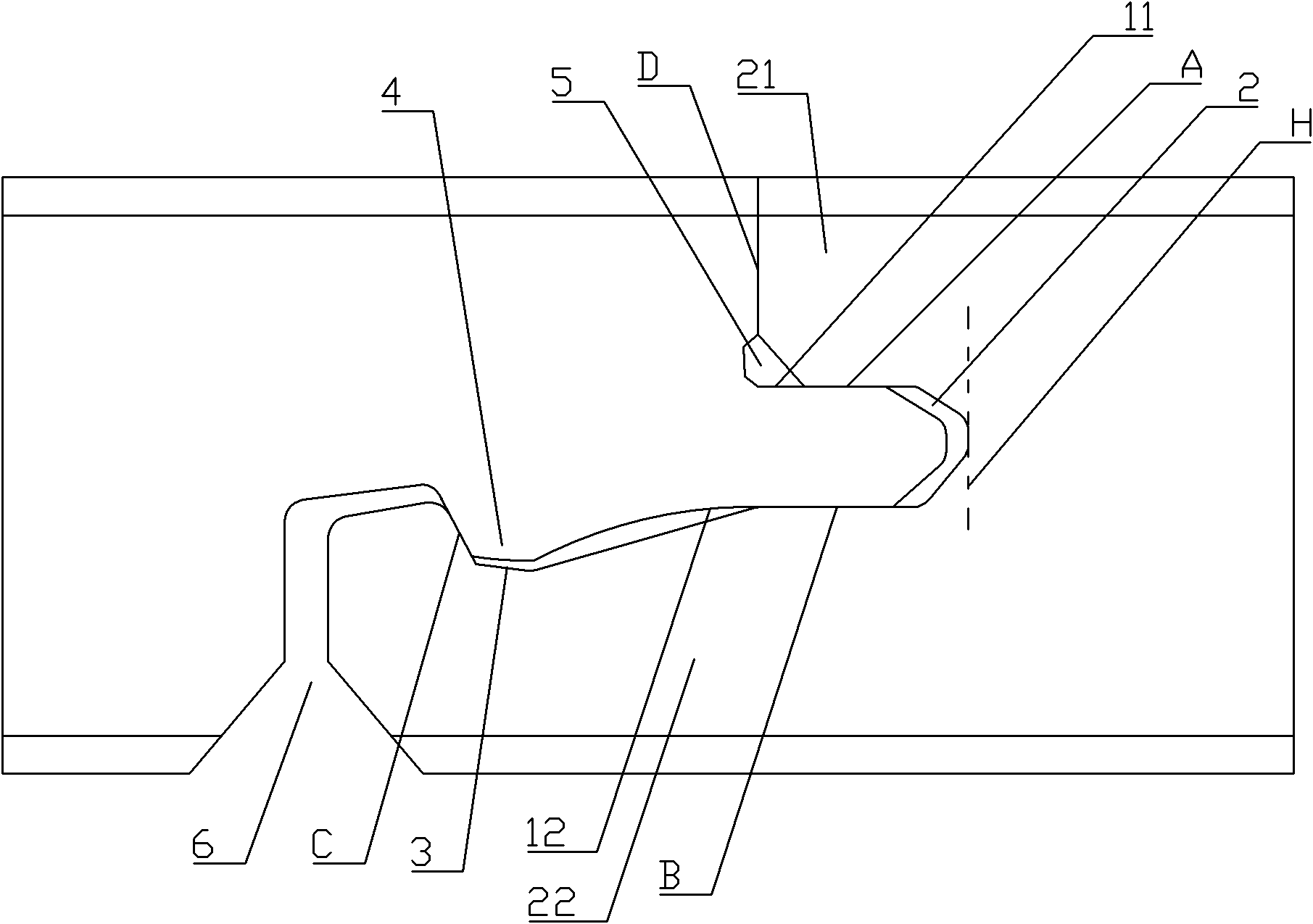
[0014] Now combined with image 3 The present invention will be described in further detail. The drawing is a simplified schematic diagram, which only illustrates the basic structure of the present invention in a schematic manner, so it only shows the structure related to the present invention.

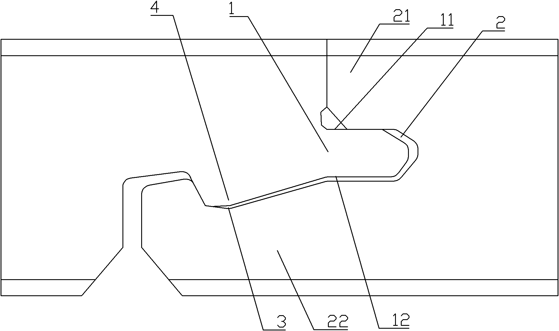
[0015] Such as image 3 As shown, a lock for cork or plastic floor includes a tongue 1 and a groove 2.

[0016] The tongue and groove 2 has an upper tongue 21 and a lower tongue 22, the tongue 1 has an upper tongue surface 11 and a lower tongue surface 12, the length of the lower tongue 22 exceeds the upper tongue 21, and the lower tongue 22 has a recess 3, There are protrusions 4 on the lower tongue surface 12, the positions of the recesses 3 and the protrusions 4 are beyond the end surface of the upper tongue 21, the tongue 1 is inserted into the groove 2, the protrusion 4 is inserted into the recess 3, the tongue 1 and the groove 2 have a horizontal lock And vertical locking, the hor...


PUM


Abstract

The invention relates to the technical field of floor latches, in particular to a latch for a cork or a plastic floor. The latch comprises a false tongue and a mortise. A horizontal lock between the false tongue and the mortise comprises a contact surface D between the surfaces of the floor and a contact surface C which is arranged between a groove and a bulge and prevents the false tongue from relieving locking from the mortise through translational motion, and a gap exists between a concave bottom and a convex bottom; a vertical lock between the false tongue and the mortise comprises a contact surface A between an upper tongue surface and an upper tenon and a contact surface B between a lower tongue surface and a lower tenon, and the contact surface A and the contact surface B do not exceed the end surface of the upper tongue. When a forming tool of floor latch slotting equipment processes the positions of the upper tenon and the lower tenon of the contact surface A and the contact surface B, the processing is carried out by taking the floor plane as the reference plane, therefore, the splicing height difference caused by the thickness of the floor is overcome; meanwhile, the gap exists between the concave bottom and the convex bottom of the floor, and the influence on the splicing height difference, which is caused by the extrusion between the bulge and the indentation, can be overcome.

Description

Technical field [0001] The invention relates to the technical field of floor locks, in particular to a lock for cork or plastic floors. Background technique [0002] The structure of the floor lock currently used is as follows figure 1 As shown, the adjustment of the height difference at the floor splicing depends on the extrusion of the upper tongue surface 11 of the tongue 1 and the upper tongue 21 of the groove 2, and the top of the protrusion 4 on the lower tongue surface 12 and the upper tongue 22 The squeeze between the bottom of the recess 3 is adjusted. [0003] However, when this kind of floor lock, which is generally used for hardwood or composite floors, is applied to cork or plastic floor, because the lower tenon 22 of the tongue and groove of the cork or plastic floor is elastic, the cork or plastic material of the above structural lock is used The floor is more prone to the height difference at the floor joints caused by the thickness of the floor substrate. [0004] ...

Claims


Application Information

Patent Timeline
IPC IPC(8): E04F15/02E04F15/04E04F15/10
Inventor 沈鸣生高建林陈建明沈时初陆斌
Owner JIANGSU LODGI WOODS IND CO LTD
Learn More