System for simulating mine environment
A kind of environment simulation and mine technology, applied in the field of simulation system, can solve the problems of unintuitive response, complexity and difficulty of being recognized, and inability to understand miners' reaction and physical condition in time, so as to reduce major production accidents and prolong life The effect of maintaining time and improving decision-making efficiency
- Summary
- Abstract
- Description
- Claims
- Application Information
AI Technical Summary
Problems solved by technology
Method used
Image
Examples
Embodiment 1
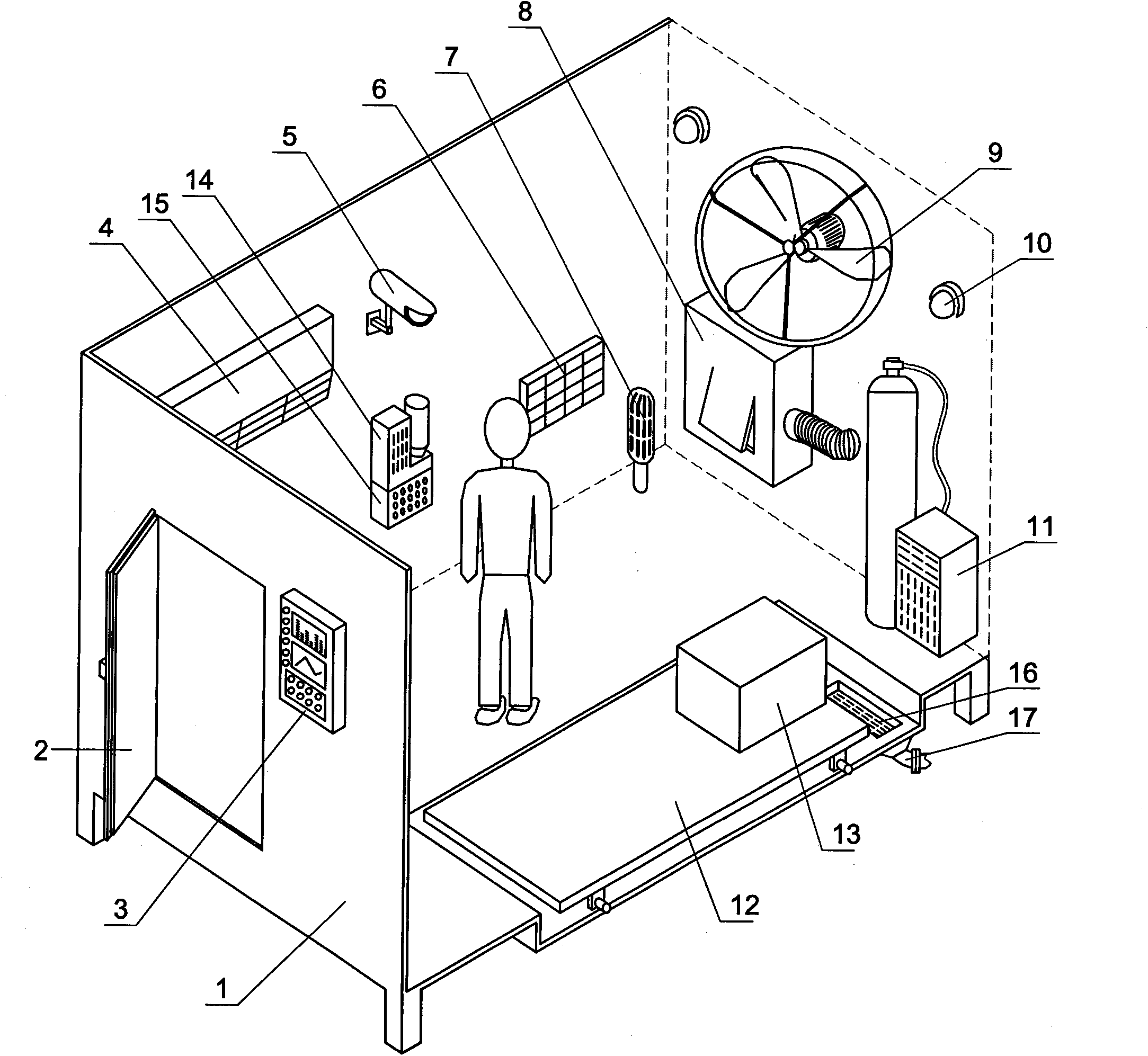
[0047] Embodiment one: see figure 1 , image 3 , in the figure, the number 1 is an airtight airtight room located on the surface, 2 is a door that can be sealed, 3 is an outdoor display and control buttons, 4 is an air conditioner, 5 is a camera, and 6 is an installation box for various sensors or detectors , 7 is a gas generator, 8 is a dust extraction device, 9 is a fan, 10 is a miner's lamp, 11 is an oxygen generator, 12 is a vibration plate, 13 is an eccentric vibration motor, 14 is a humidifier, 15 is a dryer, 16 is a drain, and 17 is a valve on the drain pipe.
[0048] A mine environment simulation system, including a sealed airtight room 1 and a door 2 arranged on the surface, when the door 2 is closed, the entire airtight room should be in a completely sealed and light-tight state, and the light-tight form can be The section wall, ceiling, and bottom surface of the airtight chamber are all made of opaque materials, or they can be made of light-transmitting materials ...
Embodiment 2
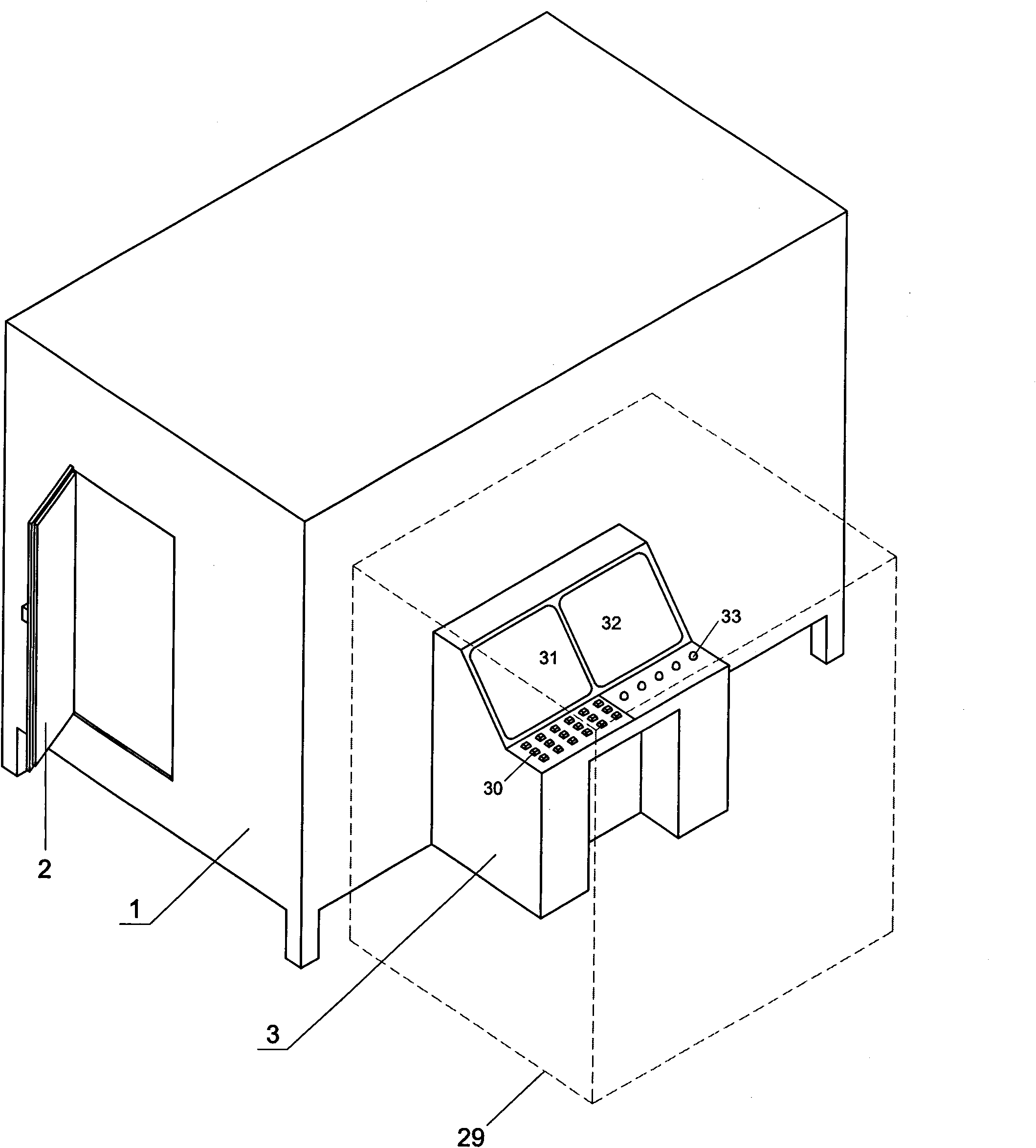
[0062] Embodiment two: see figure 2 , the content is basically the same as that of Embodiment 1, and the similarities will not be repeated. The difference is that there is also an operating room specially used for outdoor detection and control personnel outside the airtight room. The display 31 of instrument numerical value, and video player 32, control button 30, signal display lamp or warning lamp 34.
Embodiment 3
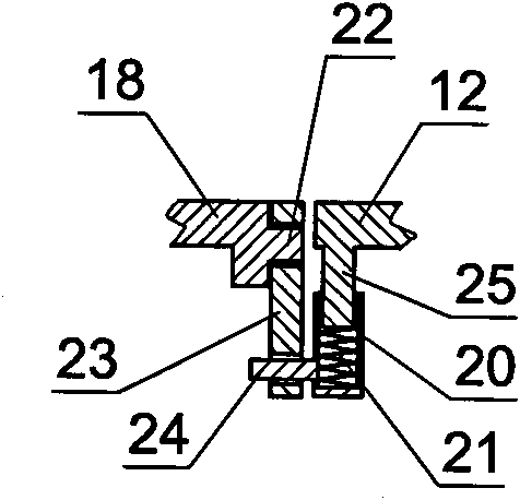
[0063] Embodiment three: see Figure 4 , Figure 5 , the content is basically the same as that of Embodiment 1, and the similarities will not be repeated, but the difference is: Figure 4 with Figure 5 On the floor 18, an upward vertical support rod 19 is fixed around the vibrating plate. On each vertical supporting plate, a pin shaft 22 is provided, and a pin shaft 24 is provided on the vibrating plate 12 side walls. The pin shafts 24 are connected by wire ropes 26 . When the eccentric vibrating motor 13 rotates on the vibrating plate 12, the vibrating plate 12 starts to swing back and forth and / or left and right, and at the same time swings up and down under the cooperation of the spring.
PUM
 Abstract
Description
Claims
Application Information
 - R&D
- Intellectual Property
- Life Sciences
- Materials
- Tech Scout
- Unparalleled Data Quality
- Higher Quality Content
- 60% Fewer Hallucinations
Browse by: Latest US Patents, China's latest patents, Technical Efficacy Thesaurus, Application Domain, Technology Topic, Popular Technical Reports.
© 2025 PatSnap. All rights reserved.Legal|Privacy policy|Modern Slavery Act Transparency Statement|Sitemap|About US| Contact US: help@patsnap.com


