Combined measuring device and method for air outlet temperature filed of wind tube

An air outlet temperature and measuring device technology, which is applied in measuring devices, radiation pyrometry, thermometers, etc., can solve the problem that the extreme temperature of the temperature field cannot be measured, the temperature field change information cannot be obtained in real time, and all the temperature fields cannot be measured. characteristics and other problems to achieve the effect of overcoming the precise temperature distribution and temperature field characteristics

Inactive Publication Date: 2011-01-05
CHINA JILIANG UNIV
View PDF5 Cites 8 Cited by
  • Summary
  • Abstract
  • Description
  • Claims
  • Application Information

AI Technical Summary

Problems solved by technology

However, this method only uses a few measurement points to characterize the temperature field, and cannot measure all the characteristics of the temperature field.
For example, when no measurement point is set in the extreme value area of ​​the temperature field, the extreme temperature of the temperature field cannot be measured
In addition, limited by the response time of the contact temperature sensor, when the wind field or temperature field changes, this measurement method cannot obtain the change information of the temperature field in real time
[0004] Although infrared radiation sensors can directly measure a two-dimensional temperature field with a certain area (traditional temperature sensors such as thermocouples and thermal resistances can only measure the temperature of a single point), they are affected by emissivity, ambient temperature, atmospheric humidity, measurement distance, and surrounding objects. Influenced by many factors such as radiation, its temperature measurement accuracy is often difficult to meet the actual temperature measurement needs

Method used


Image

  • Combined measuring device and method for air outlet temperature filed of wind tube
  • Combined measuring device and method for air outlet temperature filed of wind tube
  • Combined measuring device and method for air outlet temperature filed of wind tube

Examples


Embodiment Construction

[0019] The present invention will be further described below in conjunction with accompanying drawing.

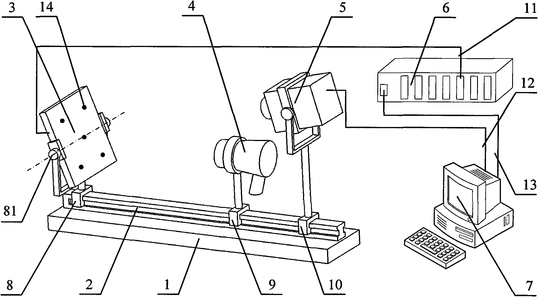
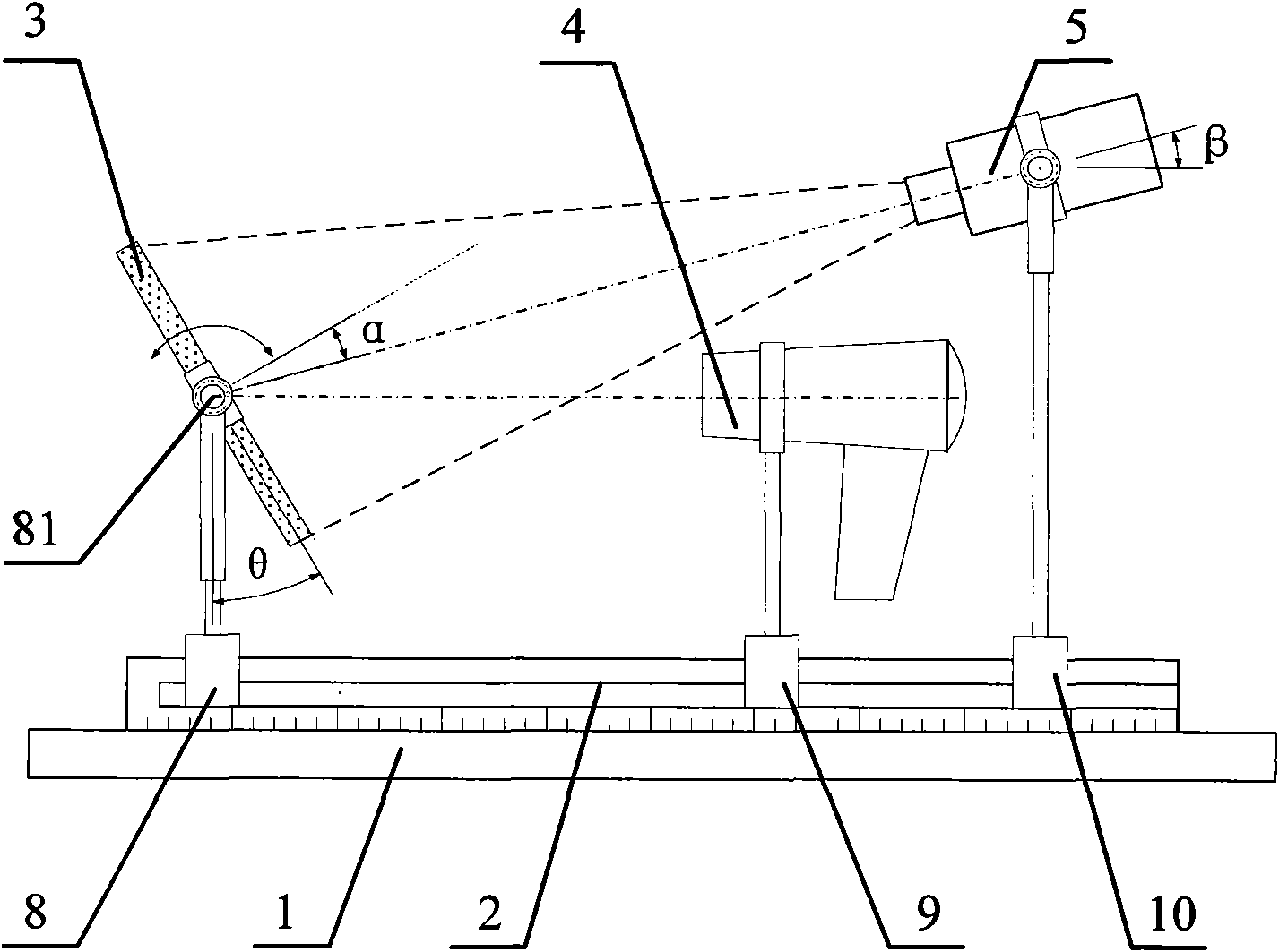
[0020] Such as figure 1 , figure 2 As shown, the measuring device of the present invention includes a base 1, a guide rail 2, a wind target 3 embedded with a thermocouple 14, a wind cylinder 4, an online thermal imaging camera 5, a first bracket 8, a second bracket 9, and a third bracket 10 , multi-channel acquisition instrument 6 and upper computer 7. Wherein, the guide rail 2 is fixed on the base 1; the first support 8 is provided with a horizontal axis 81, and the wind target 3 is installed on the horizontal axis 81, and the horizontal axis 81 passes through the geometric center of the wind target 3 and the horizontal axis 81 and the wind target 3 The normal is vertical, and the wind target 3 and the horizontal axis 81 are in rotation fit. The first bracket 8 , the second bracket 9 and the third bracket 10 are respectively installed on the guide rail 2 and form a sli...


PUM


Abstract

The invention discloses a combined measuring device and method for the air outlet temperature field of a wind tube. A lead rail is fixed on a base, and a first bracket, a second bracket and a third bracket are mounted on the lead rail and matched with the lead rail in a sliding way. A wind target is mounted on a horizontal shaft of the first bracket and rotationally matched with the first bracket; and the horizontal shaft passes through the geometrical centre of the wind target and is vertical to the normal line of the wind target. The wind tube is mounted on the lead rail through the second bracket; an online infrared thermal imager is mounted on the lead rail through the third bracket; the wind tube is located between the wind target and the online infrared thermal imager; the centre line of the wind tube passes through the geometrical centre of the wind target; the air outlet of the wind tube and the lens of the online infrared thermal imager are opposite to the measuring end of a thermocouple on the wind target; and the optical shaft of the online infrared thermal imager passes through the geometrical centre of the wind target. The lens of the online infrared thermal imager is located above the air outlet of the wind tube. The thermocouple on the wind target is electrically connected with multiple paths of collectors; and the multiple paths of collectors and the online infrared thermal imager are respectively connected with an upper computer via data lines.

Description

technical field [0001] The invention relates to a device and a method for measuring a temperature field, in particular to a combined measuring device and a method for the temperature field of an air outlet of an air duct. Background technique [0002] The hair dryer is one of the most widely used electric heating household appliances. Based on different needs, the hair dryer is mainly used for drying and shaping hair, and it can also be used for partial drying, heating and physical therapy in laboratories, physiotherapy rooms, industrial production, and art. Although the fan may have different purposes, types or functions, the temperature distribution of the temperature field is the most important and must be considered in design and use. The measurement of the temperature field is mainly divided into contact point group distribution measurement and non-contact area array direct measurement. The former measures the temperature of the measured medium based on the principle ...

Claims


Application Information

Patent Timeline
IPC IPC(8): G01J5/00G01K7/02G01K7/22
Inventor 郑恩辉陈乐孙坚高坚钟绍俊徐红伟邹超
Owner CHINA JILIANG UNIV
Why Eureka
Try Eureka