
Self-calibrating method of internal reference resistors of multi-range digital electronic measuring instrument

A technology of electronic measurement and reference resistance, applied in the direction of measuring electrical variables, measuring devices, multi-tester circuits, etc., can solve the problems that affect the improvement of product performance and price ratio, high requirements for stability and accuracy, and reduction of production costs, etc., to achieve High accuracy, simple regular calibration, and the effect of simplifying the production process

Inactive Publication Date: 2011-01-05
臧佳菁
View PDF0 Cites 26 Cited by
  • Summary
  • Abstract
  • Description
  • Claims
  • Application Information

AI Technical Summary

Problems solved by technology

[0004] The purpose of the present invention is to overcome the deficiencies in existing multi-range digital electronic measuring instruments that require high stability and accuracy of a set of internal reference resistors, make selection difficult, and affect the improvement of product performance and price ratio. Provide a self-calibration method that only needs to set a long-term stable resistance as a standard resistance to improve the measurement accuracy of the entire multi-range digital electronic measuring instrument and effectively reduce the production cost

Method used


Image

  • Self-calibrating method of internal reference resistors of multi-range digital electronic measuring instrument
  • Self-calibrating method of internal reference resistors of multi-range digital electronic measuring instrument
  • Self-calibrating method of internal reference resistors of multi-range digital electronic measuring instrument

Examples


Embodiment Construction

[0016] The present invention will be further described below with reference to the accompanying drawings and typical embodiments.

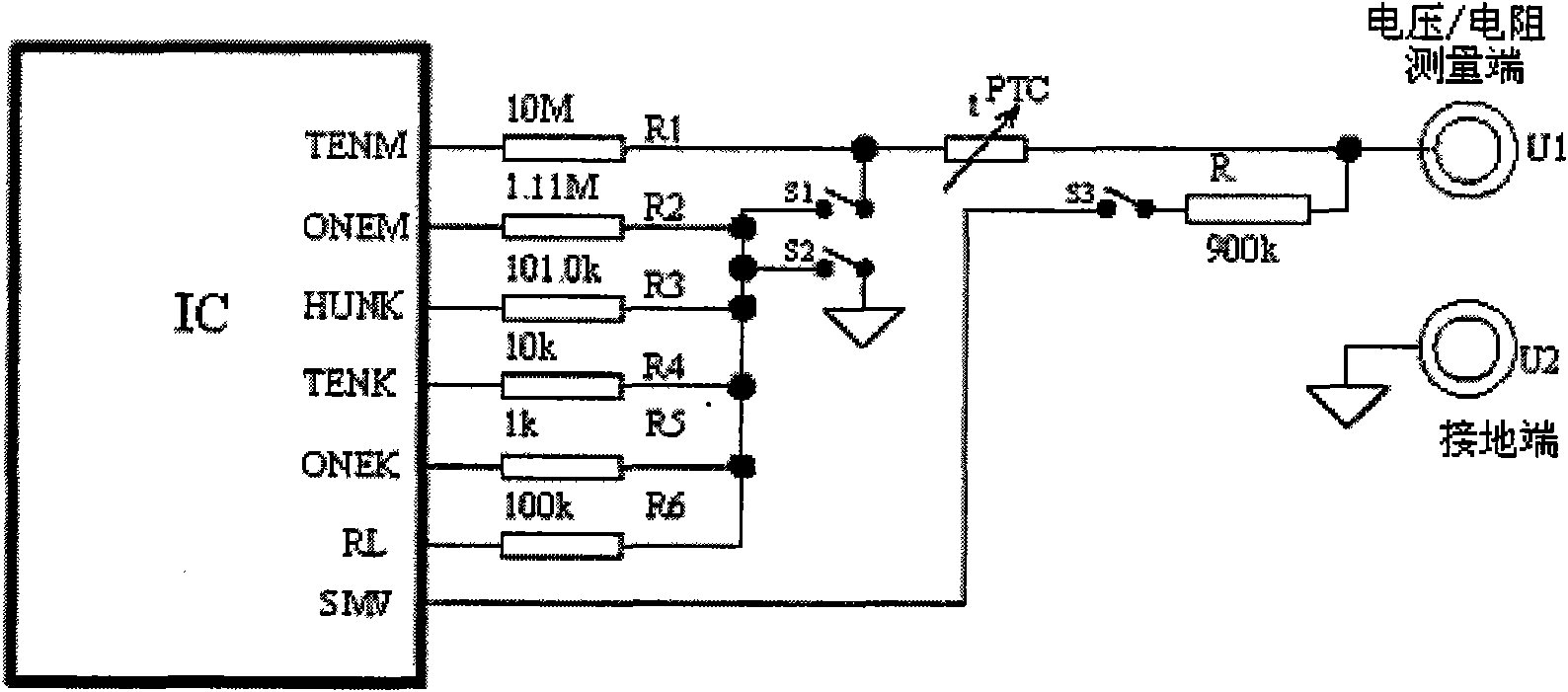
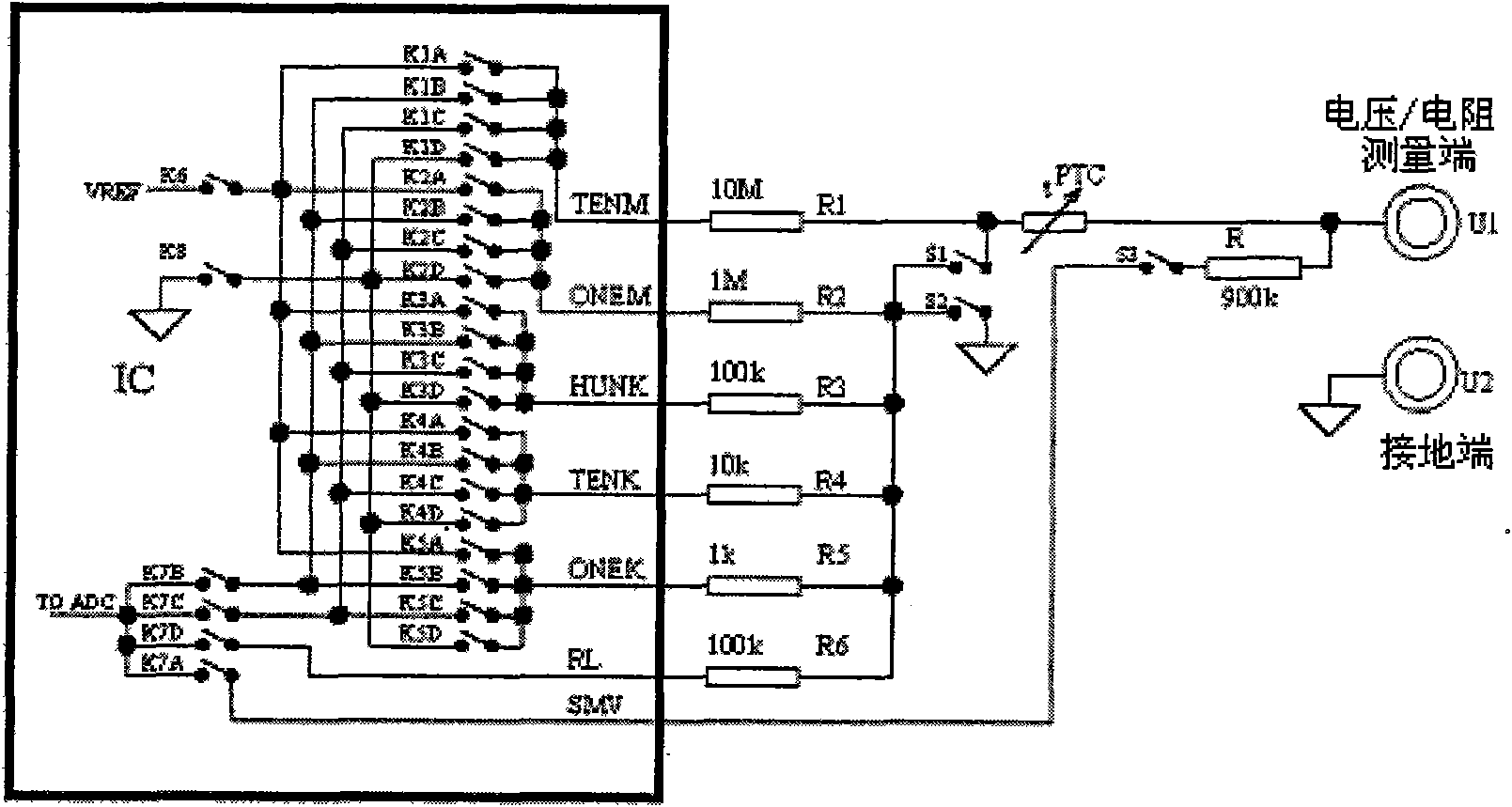
[0017] exist figure 1 and figure 2 In , take the most common automatic range digital multimeter in the multi-range digital electronic measuring instrument as an example to illustrate the existing technology and the basic working principle of the measurement. In common auto-ranging digital multimeters, the relevant circuits for resistance and voltage measurement include measurement inputs U1 and U2, integrated circuits (ICs), precision reference resistors R1-R5, and some external switches necessary to illustrate the working principle switch and auxiliary resistor. The integrated circuit (IC) includes necessary electronic switches, reference voltage sources, amplifiers, analog-to-digital converters (ADCs), microprocessors, display drive circuits, etc., where R1-R5 are precision reference resistors, and R and R6 are sampling resistance. When the...


PUM


Abstract

The invention relates to a self-calibrating method of internal reference resistors of a multi-range digital electronic measuring instrument, comprising the following steps of: on the basis of the design line of the traditional digital electronic measuring instrument, additionally setting an electronic switch and a self-calibrating program; setting a resistor with good long-term stability as an internal standard resistor in a set of internal reference resistors; when in a self-calibrating state, controlling the electronic switch by using the self-calibrating program to form different combinations so as to obtain comparing and measuring circuits among different reference resistors; and respectively and directly or indirectly comparing the reference resistors with the set internal standard resistor to measure respective actual resistance values and storing the actual resistance values in an internal storage for automatically correcting measuring results. Because only one standard resistor with good long-term stability needs to be adopted, other reference resistors are compared and calibrated with the standard resistor, and the method effectively reduces the requirements of other reference resistors, is beneficial to reducing the production cost and ensuring the measuring precision of each measuring process so that the calibration in the production process and the periodic calibration of users both are simpler and more effective and accurate.

Description

technical field [0001] The invention relates to the technical field of multi-range electronic measuring instruments, in particular to a method for self-calibrating the internal reference resistance of a digital electronic measuring instrument. Background technique [0002] At present, a common multi-range digital electronic measuring instrument, such as a digital multimeter, is provided with a standard voltage source and a set of reference resistors in the internal electrical circuit. In different measurement functions and ranges, through different combinations of electronic switches, one or more of these reference resistors are combined to form reference resistors with different equivalent resistance values ​​or voltage divider networks with different voltage divider ratios to meet the needs of Measurement requirements for different functions and ranges. Since the accuracy of these reference resistors will directly affect the accuracy of the final measurement results, it i...

Claims


Application Information

Patent Timeline
Patent Type & Authority Applications(China)
IPC IPC(8): G01R35/00G01R15/12
Inventor 臧佳菁臧玉伦
Owner 臧佳菁
Learn More