High-accuracy antenna reflecting surface panel and manufacturing method thereof

A reflective surface, high-precision technology, applied in antennas, electrical components, etc., can solve the problems of complex process, manual calibration, large internal stress, etc., to achieve the effect of simple and convenient process, increase strength and rigidity, and reduce internal stress

Active Publication Date: 2011-01-05
NO 54 INST OF CHINA ELECTRONICS SCI & TECH GRP +1
View PDF3 Cites 14 Cited by
  • Summary
  • Abstract
  • Description
  • Claims
  • Application Information

AI Technical Summary

Problems solved by technology

[0006]2. Because the Z-shaped ribs of the traditional riveting process are obtained by the Z-shaped bar through the stretch-bending process, there is stress in the panel itself. There is also stress in the middle, which causes its own internal stress to be large, and there is a hidden danger of deformation
[0007]3. The traditional aircraft skin quenching and stretching process has great difficulty in the process of manufacturing a skin with a large area and a gentle curvature. After the skin is stretched

Method used


Image

  • High-accuracy antenna reflecting surface panel and manufacturing method thereof
  • High-accuracy antenna reflecting surface panel and manufacturing method thereof
  • High-accuracy antenna reflecting surface panel and manufacturing method thereof

Examples


Embodiment Construction

[0038] Below in conjunction with accompanying drawing, the present invention is described in further detail:

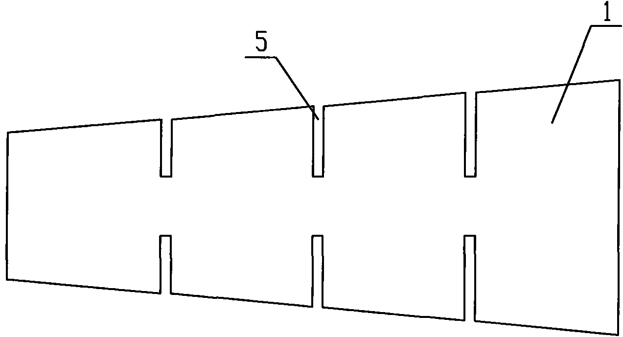
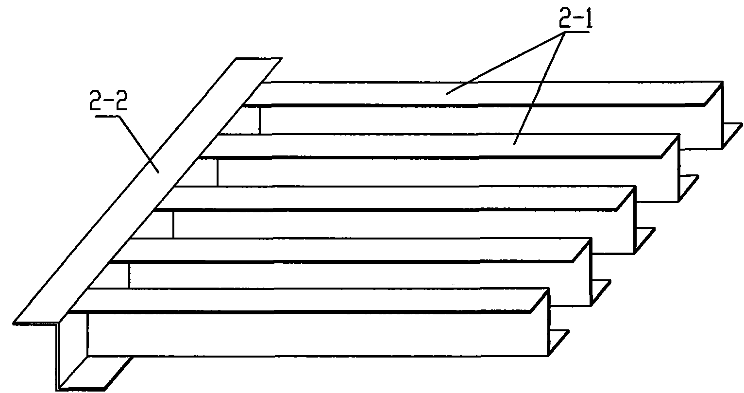
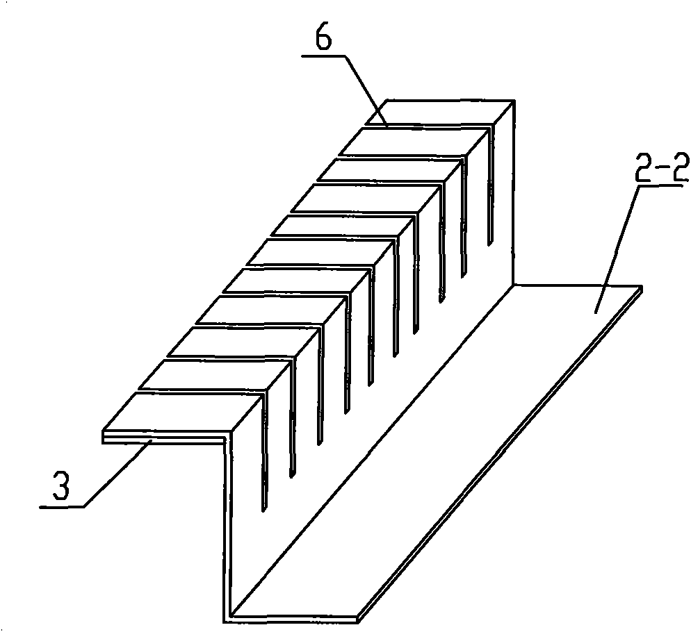
[0039] Such as Figure 1 to Figure 7As shown, the antenna reflector panel of the present invention comprises a supporting rib frame composed of skin 1, 4 Z-shaped bar ring rib beams 2-1 and 2 Z-shaped bar longitudinal rib beams 2-2; the skin 1 is fan-shaped, and the skin The front and back surfaces of 1 are the reflection surface and the support surface respectively, the Z profile ring reinforcement beam 2-1 is arranged along the circumferential direction of the skin 1, and the Z profile longitudinal reinforcement beam 2-2 is arranged along the radial direction of the skin 1, consisting of five The supporting rib frame composed of Z profile ring rib beam and two Z profile longitudinal rib beams corresponds to the shape of the support surface of skin 1, and the two are bonded and solidified by adhesive to form a whole; the radial direction on both sides of skin 1 Thre...


PUM

PropertyMeasurementUnit
Heightaaaaaaaaaa
Depthaaaaaaaaaa

Abstract

The invention discloses a high-accuracy antenna reflecting surface panel and a manufacturing method thereof, which relate to antenna reflecting surface unit manufacturing technology in the fields of satellite communication, radio measurement and control, deep space exploration, large radio telescopes and the like. The method comprises the following steps of: forming a rib beam by using a correction grooved Z-shaped section; forming a skin by grooving an aluminum alloy plate; applying negative pressure through sealing and vacuum devices; attaching separation components such as the Z-shaped section rib beam, the skin and the like to a mold and bonding, curing and molding the separation components and the mold into a whole by using an adhesive; and releasing vacuum negative pressure to form an antenna reflecting surface unit having a high-accuracy rib grooved bonded structure. The method has the advantages of high accuracy, light weight, high rigidity, high intensity, simple processing technology, stable and reliable performance, low manufacturing cost, easy realization of production environment, mass production and the like and is particularly suitable for manufacturing large and medium high-accuracy antenna reflecting surfaces in high-frequency sections.

Description

technical field [0001] The invention relates to a high-precision antenna reflector panel and its manufacturing method in the fields of satellite communication, radio measurement and control, deep space exploration, large-scale radio telescopes, etc., and is especially suitable for high-precision antenna panels working in the Ka frequency band and above the Q frequency band. Mass production of reflective surfaces. Background technique [0002] With the rapid development of communication and measurement and control technology, the working frequency band is getting higher and higher. Not only is the demand for large and medium-sized antennas more and more extensive, but also higher requirements are put forward for the accuracy of the antenna reflection surface. The main reflective surface of large and medium-sized antennas is composed of dozens or even thousands of single reflective panels. The accuracy of a single antenna reflective panel is the basis for the accuracy of the a...

Claims


Application Information

Patent Timeline
IPC IPC(8): H01Q15/14
Inventor 金超王海东李金良张万才郑元鹏郭海鹰宁晓磊
Owner NO 54 INST OF CHINA ELECTRONICS SCI & TECH GRP
Why Eureka
Try Eureka