Multipolar connector

A multi-pole connector and connector technology, applied in the direction of connection, fixed connection, two-part connection device, etc., can solve the problems of the expansion of the mutual interval between the terminal pairs, the deterioration of the electrical connection state, and the impedance mismatch, so as to reduce the impedance difference. matching effect

Active Publication Date: 2011-01-05
HOSIDEN CORP
View PDF5 Cites 13 Cited by
  • Summary
  • Abstract
  • Description
  • Claims
  • Application Information

AI Technical Summary

Problems solved by technology

[0005] In a multi-pole connector, even if a plurality of terminals are arranged in a row at the contact part that is in contact with the terminal of the corresponding connector, by dividing a row of terminals into two rows in the vicinity of the substrate mounting part and converting it into a staggered arrangement, The limitation caused by the pitch of the through holes can be alleviated, and the pitch of the terminals can be further narrowed, so that the multi-pole connector can be further miniaturized and multi-polarized. However, in

Method used


Image

  • Multipolar connector
  • Multipolar connector
  • Multipolar connector

Examples


Embodiment Construction

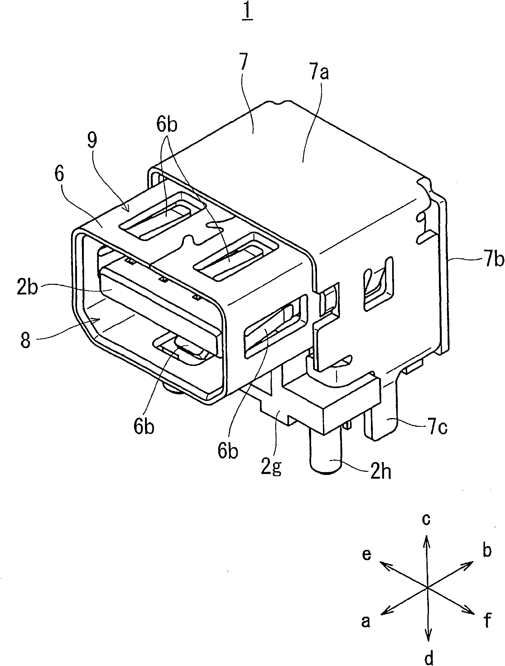
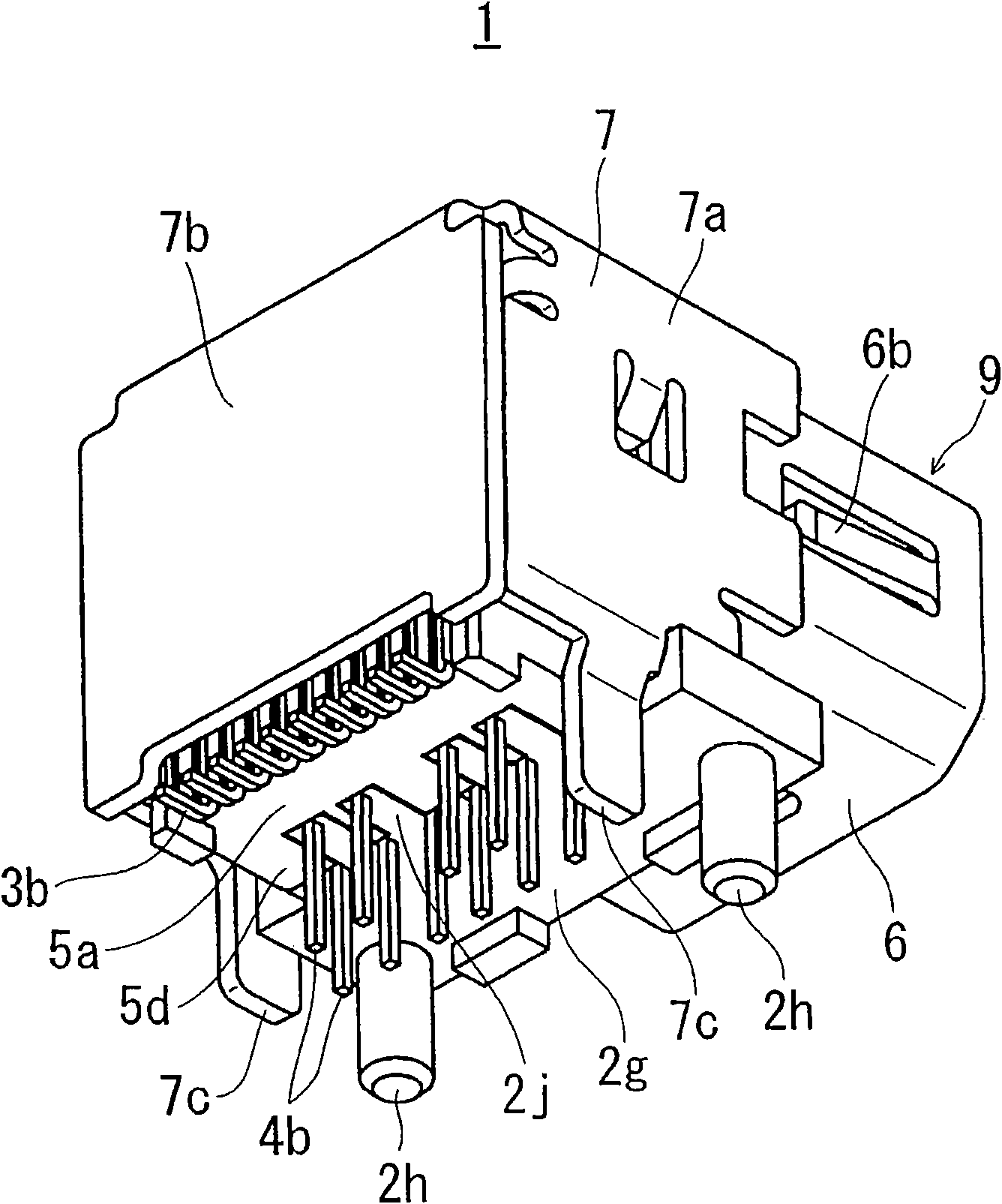
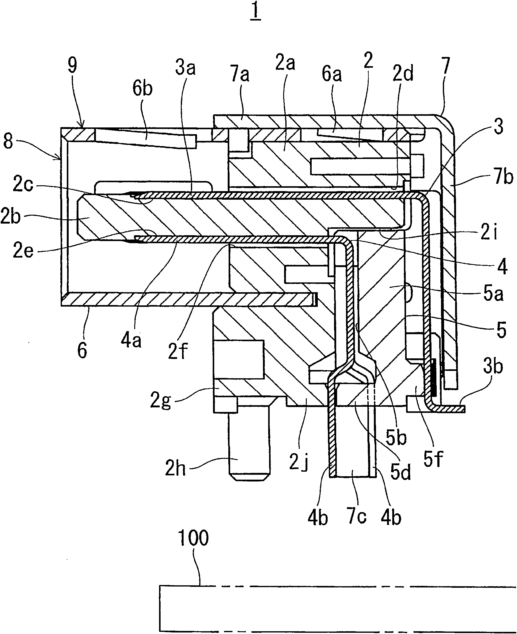
[0023] Hereinafter, one embodiment of the present invention will be described based on the drawings. figure 1 is a front perspective view of a multi-pole connector according to an embodiment of the present invention, figure 2 is a rear perspective view of the above multi-pole connector, image 3 is a cross-sectional view of the above multi-pole connector, Figure 4 It is a front perspective view of the disassembled state of the said multi-pole connector. Figure 1 ~ Figure 4 The shown multi-pole connector 1 is mounted on a printed circuit board 100 on the equipment side (refer to image 3 ) is a horizontal type for a corresponding connector not shown in the figure (a plug installed at the end of the connecting line between devices) to be inserted and fitted in parallel with the printed circuit board 100 (the vertical type is for the printed circuit board 100 A mini display port connector (mini display port connector) (socket) that is inserted vertically into the fitting me...


PUM


Abstract

The invention provides a multipolar connector in which one terminal row can be divided into a plurality of rows (row conversion) while reducing an impedance mismatch. A multipolar connector (1) which is to be insert-mounted on a printed circuit board (100) includes a terminal group (40) in which a plurality of terminals (4) are arranged in one row in contact portions (4a) with respect to terminals of a counter connector, and, while being then passed through a row converting portion (45), one terminal row (41) is divided into a plural-row portion (44) consisting of two rows (42, 43) and functioning as a connecting portion that is opposite to the counter connector, and row-converted to a substantially zigzag arrangement. The terminal group (40) includes two specific terminals (46, 47) in which, in the plural-row portion (44), the terminal width (L1) is wider than the terminal width (L2) of the contact portions (4a). The two specific terminals (46, 47) constitute a terminal pair for transmitting differential signals.

Description

technical field [0001] The present invention relates to a multi-pole connector, in particular to a multi-pole connector mounted on a printed circuit board and having a plurality of terminals for insertion and installation. Background technique [0002] In the case where a plurality of terminals for plug-in mounting of the multi-pole connector are arranged in a row at the contact parts that contact the terminals of the corresponding connector, the substrate mounting parts of the terminals for plug-in mounting are also arranged in a row and protrude outward. , and the substrate mounting portions of the terminals are inserted and soldered into through holes arranged in a row on the printed circuit board (for example, refer to Patent Document 1). [0003] Although there is a strong demand for miniaturization and multi-polarization of multi-pole connectors, there is a problem that even if the existing multi-pole connectors are to be further miniaturized and multi-polarized, the p...

Claims


Application Information

Patent Timeline
IPC IPC(8): H01R13/02H01R12/71
CPCH01R12/58H01R23/7073H01R12/712
Inventor 近藤快人佐佐木大辅
Owner HOSIDEN CORP
Why Eureka
Try Eureka