Apparatus for conveying electronic element

A technology for electronic components and conveying devices, which is applied to electrical components, electrical components, conveyor objects, etc., can solve the problems of low conveying efficiency, electronic component adsorption, and increased time required for placement, so as to reduce the number of components and shorten the conveying time. , the effect of reducing manufacturing costs

Active Publication Date: 2011-01-05
TESEC
View PDF0 Cites 12 Cited by
  • Summary
  • Abstract
  • Description
  • Claims
  • Application Information

AI Technical Summary

Problems solved by technology

However, in this way, the time required for the adsorption and placement of electronic components will increase, and the transfer efficiency will also decrease.

Method used


Image

  • Apparatus for conveying electronic element
  • Apparatus for conveying electronic element
  • Apparatus for conveying electronic element

Examples


Embodiment 1

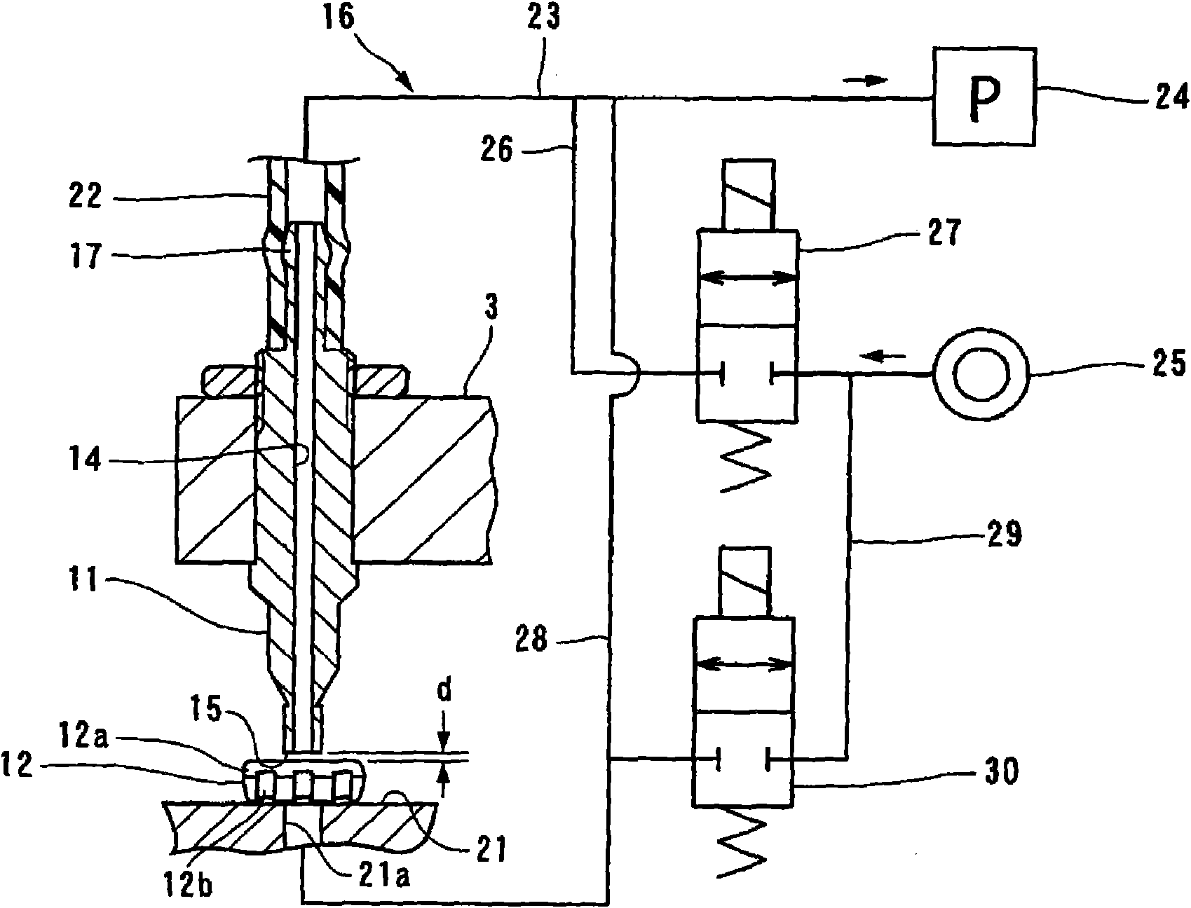
[0100] The electronic component 12 conveyed by the conveying device 1 shown in the above embodiment has a weight of 3 g or less, and the protruding length of the lead 12 b protruding downward from the bottom surface of the packaging portion 12 a is 0.1 mm or less. In addition, the vacuum pressure when the pick-and-place device 11 picks up the electronic component 12 is -40~-60kpa (absolute vacuum is -101.3kpa).

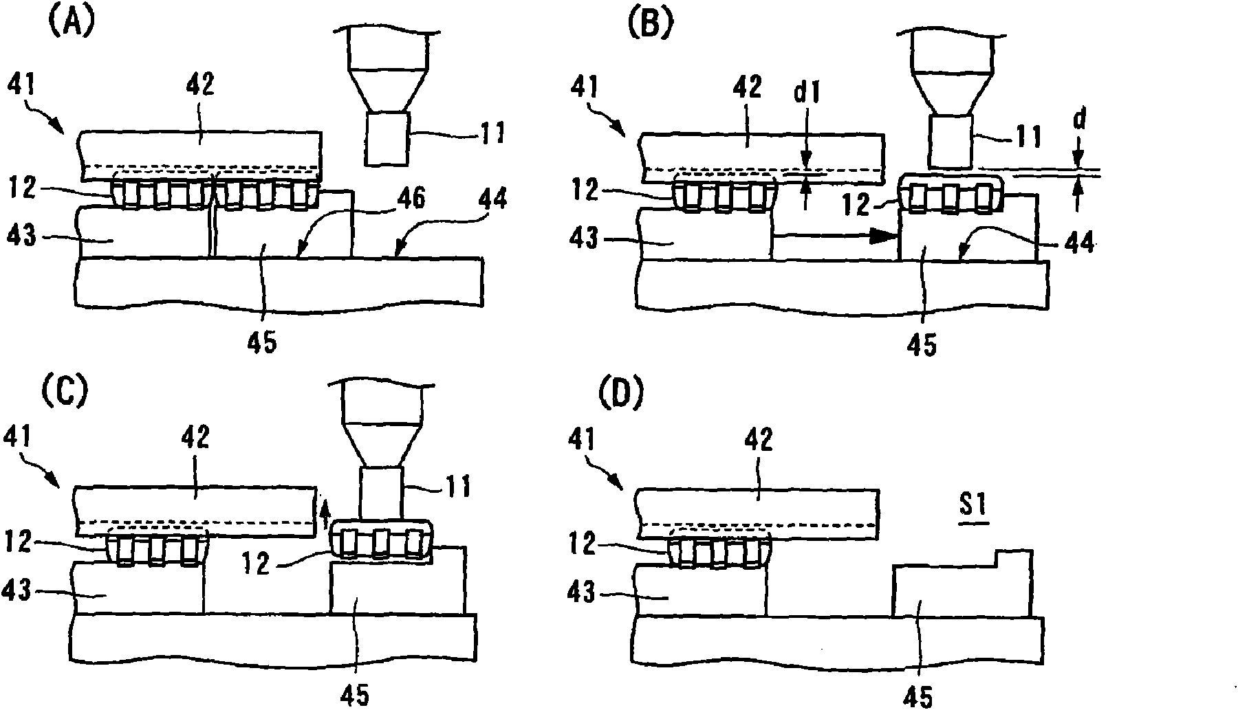
[0101] The gap d between the slider 45 of the electronic component supply unit 41 and the suction pick-and-place device 11 was 0.2 mm.

[0102] The gap d between the electronic component 12 held by the support member 53 of the labeling device 7 and the suction pick-and-place device 11 is 0.4 mm.

[0103] In addition, these numerical values ​​are just an example, and can be changed suitably according to the kind of the electronic component 12 used as a target.


PUM


Abstract

Provided is an apparatus for conveying an electronic element, capable of ensuring the electronic element to be conveyed with high efficiency and without damage. The apparatus includes a first handover part containing the electronic element (12), a second handover part for moving and placing the electronic element (12), an adsorption picking / placing device (11) for absorbing the electronic element, a suction device (16), and a moving device (tilting stand (3), drive device (13)) for moving the adsorption picking / placing device (11) horizontally. The adsorption picking / placing device (11) is fixed on the moving device without movement up and down. The suction device (16) starts to attract when the adsorption picking / placing device (11) is arranged above the first handover part, and stops attracting when the adsorption picking / placing device (11) is arranged above the second handover part. Moving spaces (S1-S5) where the electronic element (12) and the adsorption picking / placing device (11) can be moved horizontally are formed between the first and the second handover parts.

Description

technical field [0001] The present invention relates to a conveying device for electronic components that absorbs and conveys electronic components with a suction pick-and-place device. Background technique [0002] As such a conventional conveying device, it is described in Patent Document 1, for example. The conveying device for electronic components disclosed in Patent Document 1 includes a lifting device for raising and lowering a suction pick-and-place device that picks up electronic components, and a moving device for moving the suction pick-and-place device in a horizontal direction. [0003] When the suction pick-and-place device is driven by the moving device to move in the horizontal direction, the lifting device keeps the suction pick-and-place device in a raised position. In addition, the lifting device lowers the suction pick-and-place device when the electronic component is picked up by the suction pick-and-place device, or when the electronic component is pla...

Claims


Application Information

Patent Timeline
IPC IPC(8): H05K13/02B65G47/91B25J15/06
Inventor 野泽宏和须贺胜彦
Owner TESEC
Why Eureka
Try Eureka