Backlight unit and liquid crystal display device

A technology for backlight units and liquid crystal display panels, applied in optical components, lighting devices, optics, etc., can solve the problems of easy warping of the mounting substrate 111 and inability to completely cope with heat dissipation of the heat sink, and improve the degree of freedom of configuration and the degree of freedom Effect

Active Publication Date: 2011-01-05
SHARP KK
View PDF6 Cites 17 Cited by
  • Summary
  • Abstract
  • Description
  • Claims
  • Application Information

AI Technical Summary

Problems solved by technology

[0005] However, when the backlight unit 149 is used for a long time, heat dissipation cannot be completely solved only by using the heat sink 171 and the heat dissipation substrate 172, for example, the mounting substrate 111 is easy to warp.

Method used


Image

  • Backlight unit and liquid crystal display device
  • Backlight unit and liquid crystal display device
  • Backlight unit and liquid crystal display device

Examples


Embodiment approach 2

[0124] Embodiment 2 will be described. In addition, components having the same functions as those used in Embodiment 1 are given the same reference numerals and their descriptions are omitted.

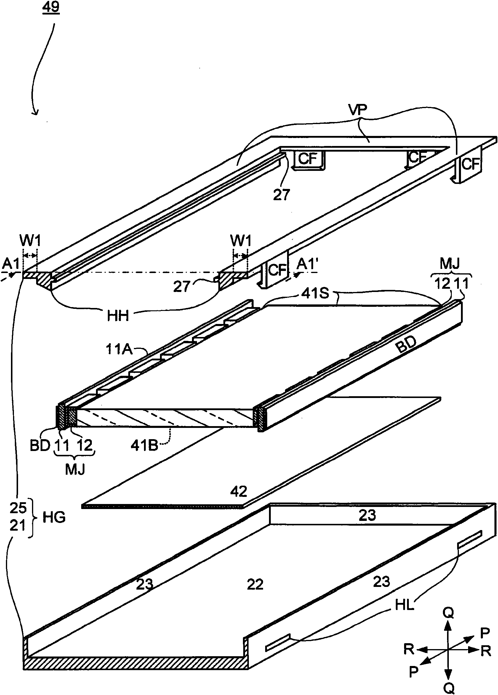
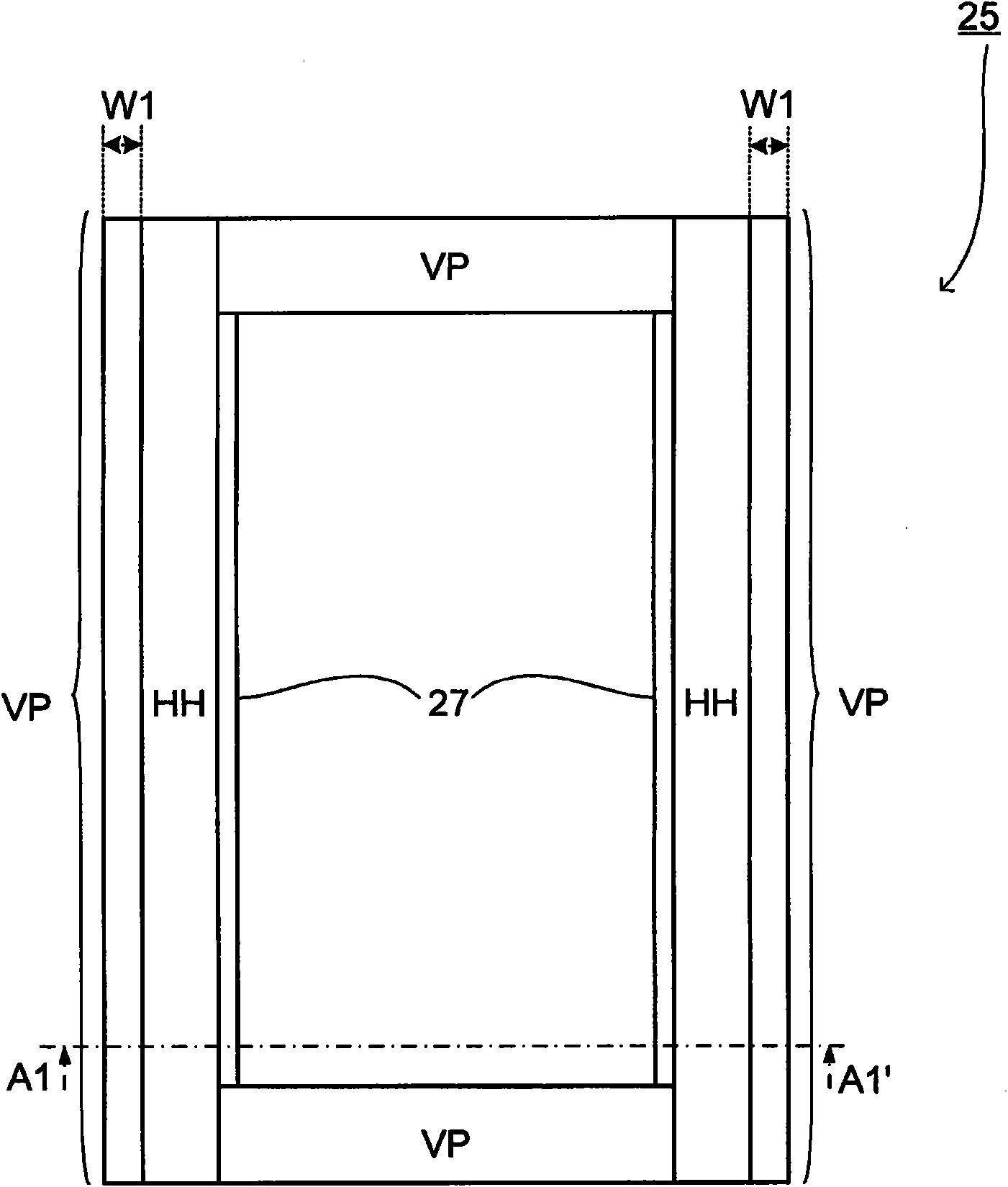
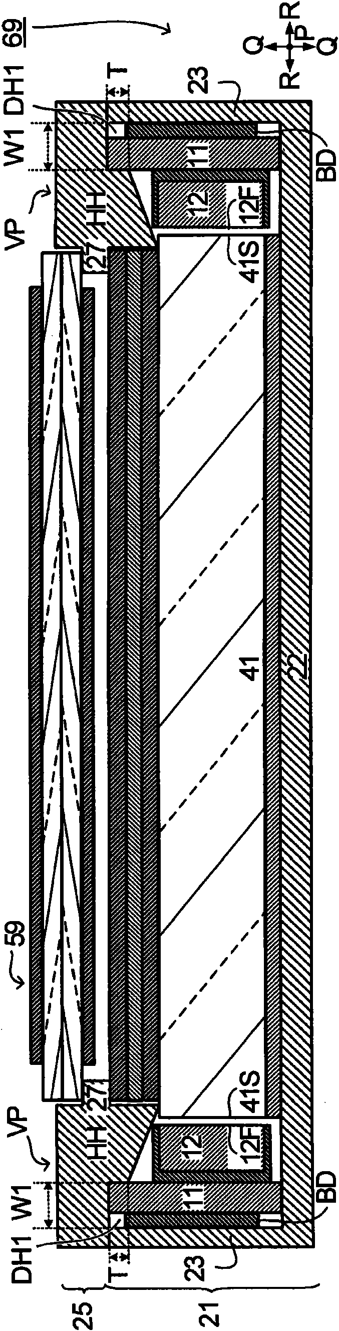
[0125] In the backlight unit 49 described in Embodiment 1, the mounting substrate 11 is sandwiched by the first groove DH1 defined by the side VP of the top-shaped housing 25 and the wall of the bottom-shaped housing 21 . 23 formed. In this embodiment 2, with Figure 11 and Figure 12 A case where the mounting substrate 11 is sandwiched by the second grooves (second grooves) DH2 other than the first groove DH1 will be described.

[0126] also, Figure 11 become with figure 1 in the same manner, Figure 12 become with image 3 in the same manner (in addition, Figure 12 The direction of the section is Figure 11 The direction indicated by the arrow at line A4-A4' of the

[0127] as it should Figure 11 and Figure 12 As shown, the second groove DH2 includes, as a part, a st...


PUM


Abstract

A housing (HG) for a backlight unit (49) includes a bottom section (22), a wall section (23) and a side section (VP), and the side section (VP) is at least a part of a first groove (DH1) which sandwiches a mounting substrate (11).

Description

technical field [0001] The present invention relates to a backlight unit including a mounting substrate on which light emitting elements are mounted, and a liquid crystal display device including the backlight unit. Background technique [0002] Conventionally, various backlight units for supplying light to a liquid crystal display panel (non-emissive display panel) of a liquid crystal display device have been developed. Typically a backlight unit includes a light source that emits light. For example, the backlight unit 149 disclosed in Patent Document 1, such as Figure 25 As shown in the cross-sectional view of , an LED (Light Emitting Diode; light emitting diode) 112 mounted on a mounting substrate 111 is used as a light source. Furthermore, the LED 112 injects light into the light guide plate 141 , and the light travels toward the liquid crystal display panel 159 through the light guide plate 141 , the reflection sheet 142 , and the optical sheet group 146 . [0003] T...

Claims


Application Information

Patent Timeline
Patent Type & Authority Applications(China)
IPC IPC(8): F21S2/00G02F1/13357F21Y101/02
CPCG02F1/133308G02F1/133615G02B6/0046G02F2001/133322G02B6/0091G02B6/0085G02F1/133322
Inventor 滨田哲也
Owner SHARP KK
Why Eureka
Try Eureka