Device on carding machine having cylinders, working elements and adjustable holding elements

A technology for working components and holding components, applied in fiber processing, deburring devices, textiles and papermaking, etc., to achieve enhanced cooling effect, improved safety, fast closed-loop and open-loop control

Active Publication Date: 2014-12-24
TRUETZSCHLER GRP SE
View PDF7 Cites 0 Cited by
  • Summary
  • Abstract
  • Description
  • Claims
  • Application Information

AI Technical Summary

Problems solved by technology

However, larger carding gauges can produce undesired neps in the carded sliver

Method used


Image

  • Device on carding machine having cylinders, working elements and adjustable holding elements
  • Device on carding machine having cylinders, working elements and adjustable holding elements
  • Device on carding machine having cylinders, working elements and adjustable holding elements

Examples


Embodiment Construction

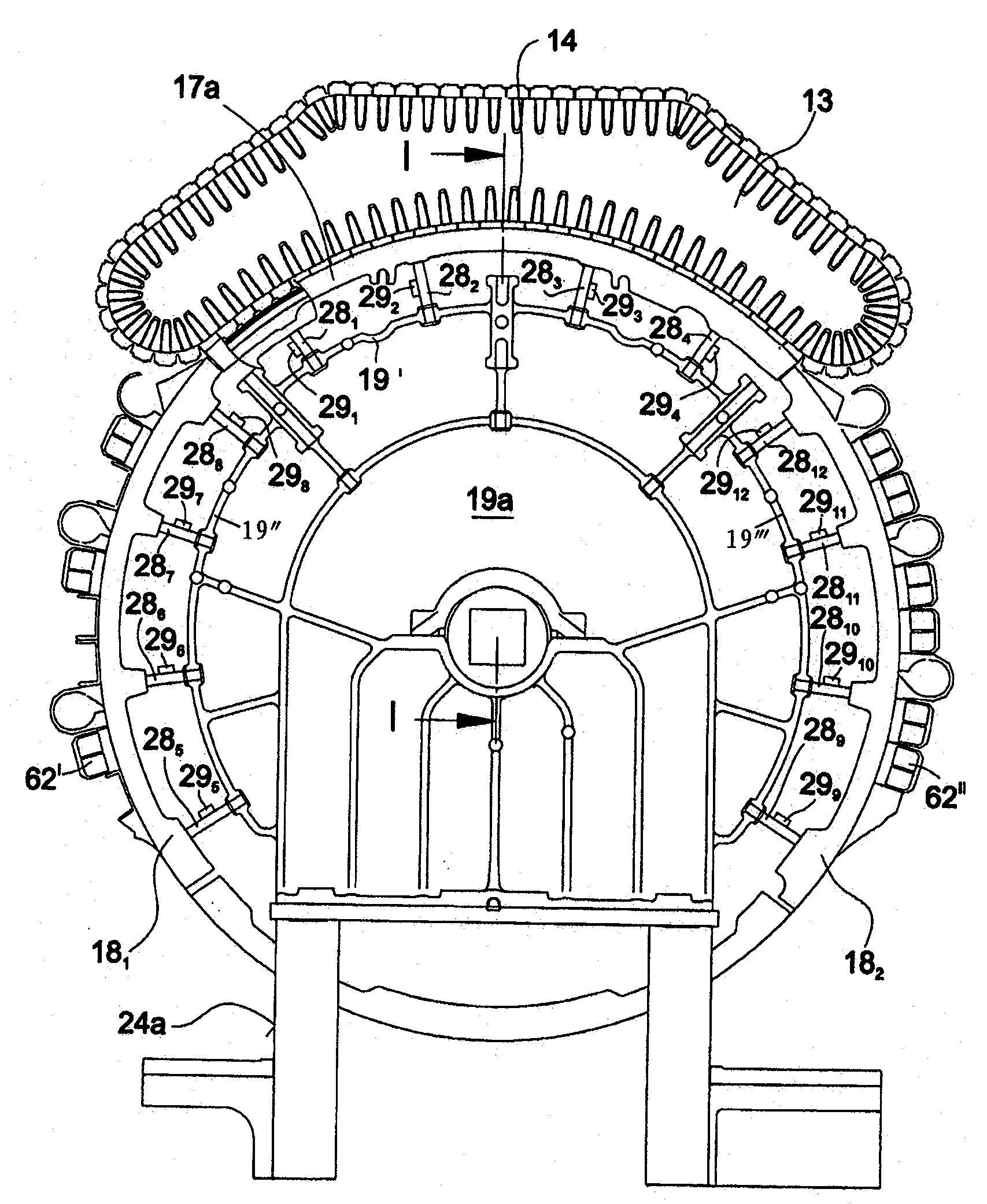
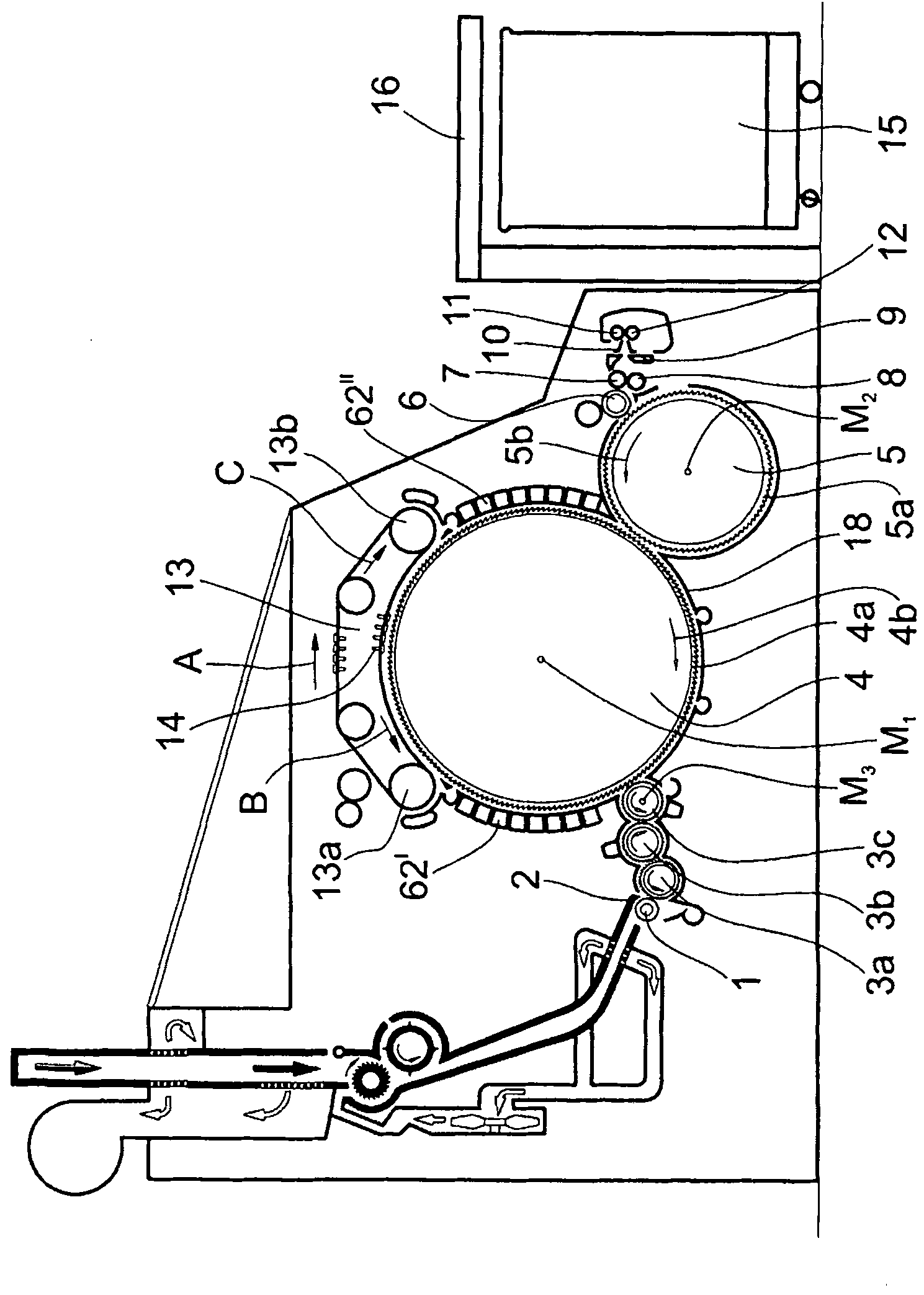
[0028] figure 1 The indicated carding machine is, for example, the flat carding machine TC07 of Trufischer (Trützschler), which has a feed roller 1, a feed plate 2, licker-in rollers 3a, 3b, 3c, cylinder 4, doffer 5, stripping Roller 6, clamping roller 7, 8, cotton web guide 9, bar guide horn 10, delivery roller 11, 12, rotary carding top 13 with card top (card top) cotton guide roller 13a, 13b, Carding flat 14, can 15 and coiler 16. The direction of rotation of the rollers is indicated by a curved arrow. Reference sign M 1 Indicates the center point (axis) of the cylinder, M2 Indicates the center point of the doffer 5, M 3 Indicates the center point of the licker-in roller 3c. The reference numeral 4a designates the card clothing, and the reference numeral 4b designates the direction of rotation of the cylinder 4 . The reference numeral 5a designates the card clothing, and the reference numeral 5b designates the direction of rotation of the doffer 5 . Reference sign B r...


PUM


Abstract

Apparatus on a carding machine for setting the working spacing between a clothed cylinder and a clothed or non-clothed working element such as a setting bend 17a, for revolving card flats 14 or setting bend 182 for fixed carding elements 62", comprises an adjustment device 28 operable by supplying and / or actively dissipating thermal energy. The device may move bends to compensate for changes in the working spacing caused by thermal or centrifugal effect.. The adjustment device may comprise a peltier effect device 29 attached to an aluminium low mass tube to heat or cool the tube to effect the compensation. Alternatively a high volumetric expansion coefficient fluid (44, figure 5) may be heated or cooled using a Peltier device (29) to cause activation of a spring biased piston (42). In an emergency the cooling effect of compressed air may be used to cool the adjusting device. A closed loop control circuit may be used to regulate the energy supply of the Peltier device.

Description

technical field [0001] The invention relates to an arrangement on a card with a cylinder, working elements with and / or without clothing and adjustable holding elements which determine the clothing of the cylinder The distance from the working element is provided with adjustment means for the working element to compensate for variations in said distance during operation, wherein said adjustment means can be operated by supplying thermal energy and is provided with at least one positioning element, such as pole. Background technique [0002] The effective distance between the tip of the clothing and the machine elements situated opposite said clothing is called the carding gauge. The aforementioned elements can likewise have a clothing, but can also be formed by a housing part with a guide surface. The carding gap is crucial for carding quality. The size (width) of the carding gauge is an important machine parameter which reflects the technical (fiber processing) and workin...

Claims


Application Information

Patent Timeline
Patent Type & Authority Patents(China)
IPC IPC(8): D01G15/28D01G15/12
CPCD01G15/30
Inventor B·雅各布斯R·皮舍尔
Owner TRUETZSCHLER GRP SE
Why Eureka
Try Eureka