
Engine ignition coil and primary winding thereof

A technology for ignition coils and primary windings, applied in transformers, inductive energy storage devices, electrical components, etc., can solve problems such as inability to make better use of the internal structure of ignition coils, large potential differences, and coil failures, so as to improve stability and prolong The effect of service life and increased insulation distance

Active Publication Date: 2011-01-12
UNITED AUTOMOTIVE ELECTRONICS SYST
View PDF8 Cites 1 Cited by
  • Summary
  • Abstract
  • Description
  • Claims
  • Application Information

AI Technical Summary

Problems solved by technology

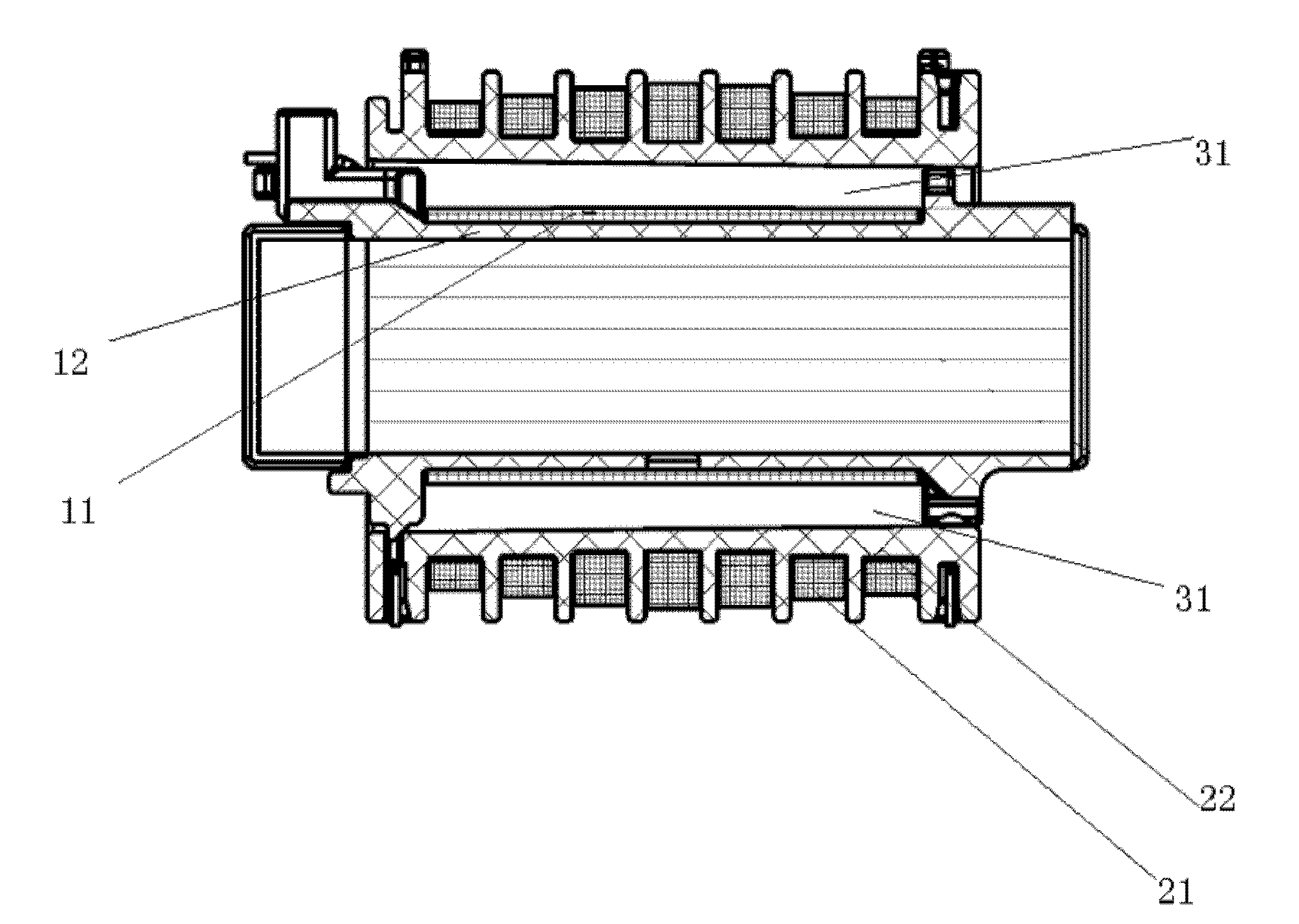
[0003] When the engine ignition coil is working, the two ignition voltage output ends of the secondary coil 21 alternately generate an ignition voltage of about 30 kV, so the maximum potential difference between the secondary coil 21 and the primary coil 11 is located at the two ignition voltage output ends of the secondary coil 21, which is about 30 kV. The minimum point of potential difference is about 15kV in the middle of the coil, and the internal structure of the ignition coil cannot be better utilized. If the insulation distance is increased, the potential difference between the two ignition voltage output terminals of the secondary coil 21 and the primary coil 11 will be too large, resulting in high voltage breakdown. causing the coil to fail

Method used


Image

  • Engine ignition coil and primary winding thereof
  • Engine ignition coil and primary winding thereof
  • Engine ignition coil and primary winding thereof

Examples


Embodiment Construction

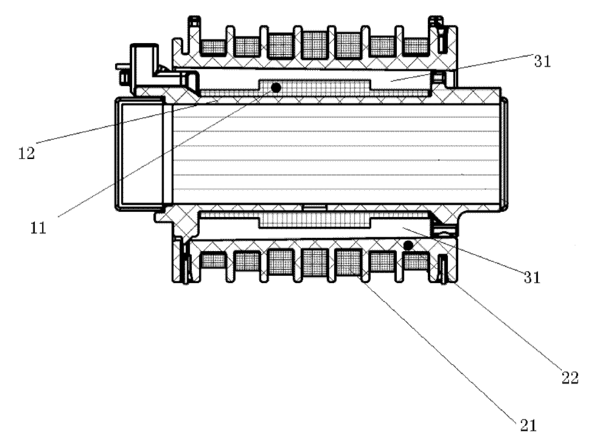
[0021] An embodiment of the engine ignition coil of the present invention is as image 3 As shown, including primary winding and secondary winding;

[0022] Secondary winding comprises secondary frame 22, secondary coil 21, and secondary winding is to wind enameled wire on secondary frame 22 as secondary coil 21, and the two ends of the enameled wire wound on secondary frame 22 are from secondary frame 22 Both ends lead out as the secondary coil ignition voltage output;

[0023] The primary winding includes a primary skeleton 12 and a primary coil 11. The primary winding is to wind an enameled wire on the primary skeleton 12 as the primary coil 11. The primary coil 11 is placed in the cavity formed by the inner wall of the secondary skeleton 22 of the secondary winding and the primary coil 11 is the same as There is an insulating distance between the inner walls of the secondary skeleton 22, and the insulating resin 31 is potted between the insulating distances;

[0024] The...


PUM


Abstract

The invention discloses an engine ignition coil which comprises a primary winding and a secondary winding, wherein the secondary winding is characterized in that a lacquered wire is wound on a secondary frame to be used as a secondary coil; two ends of the lacquered wire wound on the secondary frame are led out of two ends of the secondary frame to be used as ignition voltage output ends of the secondary coil; the primary winding is characterized in that a lacquered wire is wound on a primary frame to be used as a primary coil; the primary coil is arranged in a cavity formed by the inner wallof the secondary frame of the secondary winding, and an insulation distance is reserved between the primary coil and the inner wall of the secondary frame; and the insulation distance between the middle part of the primary coil and the inner wall of the secondary frame is less than the insulation distance between each of the two ends of the primary coil and the inner wall of the secondary frame. The invention discloses a primary winding of an engine ignition coil. The engine ignition coil of the invention can increase the insulation strength under the condition of effectively ensuring that the ignition voltage output of the secondary coil is constant.

Description

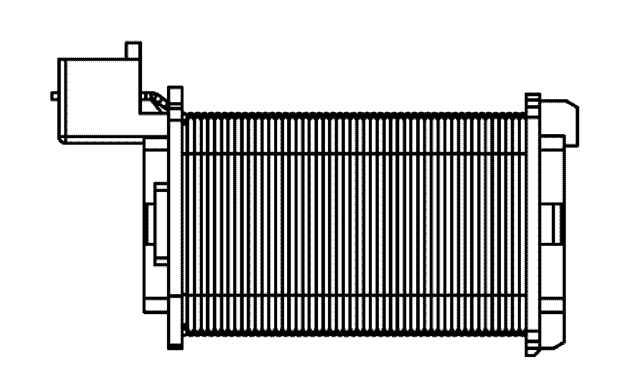
technical field [0001] The invention relates to automobile electronic technology, in particular to an engine ignition coil and its primary winding. Background technique [0002] Common engine ignition coils, such as figure 1 As shown, it includes a secondary winding and a primary winding; the secondary winding includes a secondary skeleton 22 and a secondary coil 21, and the secondary winding is to wind an enameled wire on the secondary skeleton 22 as the secondary coil 21, and the secondary winding is wound on the secondary skeleton 22 The two ends of the enameled wire are drawn from the two ends of the secondary skeleton 22 as the output end of the secondary coil ignition voltage; the primary winding such as figure 2 As shown, including the primary frame 12 and the primary coil 11, the enameled wire is evenly wound on the primary frame 12 as the primary coil 11, and the two ends of the primary frame 12 have the same layers of enameled wire as the middle part, and the pri...

Claims


Application Information

Patent Timeline
IPC IPC(8): F02P3/04H01F38/12
Inventor 孙晓庆程毅郜业猛
Owner UNITED AUTOMOTIVE ELECTRONICS SYST
Learn More