Fixing device

A technology of fixing device and locking element, applied in the direction of threaded fasteners, thin plate connections, connecting components, etc., can solve the problems of inaccurate alignment and assembly, labor-hours, trouble, etc. The effect of manufacturing quality and yield

Inactive Publication Date: 2011-01-12
王国仲
View PDF0 Cites 8 Cited by
  • Summary
  • Abstract
  • Description
  • Claims
  • Application Information

AI Technical Summary

Problems solved by technology

[0004] see Figure 8 As shown, it is a side view sectional view of the existing assembly state. It can be clearly seen from the figure that the existing cap A is combined with a screw B and an elastic body C, and is assembled with a fixing seat D so that it is not easy to fall , the lost positioning device, the positioning device can be used to pick up the cap A manually, align the front end of the fixing seat D and place it in the perforation E1 of the plate E, and at the same time put the welding ring on the fixing seat D The wall of D1 is welded and fixed with the solder paste E2 brushed around the perforation E1, so as to achieve the fixation seat D and fix the screw B and elastic body C on the plate E to prevent falling and loss, but this manual assembly method , Welding is more troublesome and quite labor-intensive and not in line with work efficiency; therefore, the general practice of the industry is often to pick up the cap A by means of automatic mechanical pick-up, and align the front end of the fixing seat D and place it on the plate In the perforation E1 of E, in order to avoid the swaying of the fixed seat D that cannot be assembled accurately, a Teflon collar F is combined between the fixed seat D and the cap A as a temporary fixing structure to The collar F is squeezed into the round hole at the front end of the fixing seat D, and is tightly fixed on the outside of the screw B as a limit, so that the screw B and the sleeve cap A are stably positioned on the fixing seat D, so that the fixing seat D can be welded on the In the perforation E1 of the plate E, when the positioning device is integrally welded on the plate E through a tin furnace, the sleeve cap A can be rotated and linked with the screw B to release the collar F from the fixing seat D, but this collar F to make the sleeve cap A and the fixed seat D temporarily socket, in addition to the need for a second cumbersome assembly process, and must also exert a large force when assembling and matching, resulting in inconvenience and difficulty in assembly, and because of The collar F made of Teflon is easy to be over-extruded and deformed by force, and even cause deformation or misalignment of the fixed seat D and cap A during use, which affects the overall assembly and the positioning effect is not good. Indeed, therefore, how to effectively solve the above-mentioned existing deficiencies and deficiencies is the direction that those engaged in this industry urgently want to improve

Method used


Image

  • Fixing device
  • Fixing device
  • Fixing device

Examples


Embodiment Construction

[0022] In order to achieve the above-mentioned purpose and effect, the technical means adopted in the present invention and its structure, the drawings are described in detail with respect to the preferred embodiments of the present invention. Its features and functions are as follows, so that it can be fully understood.

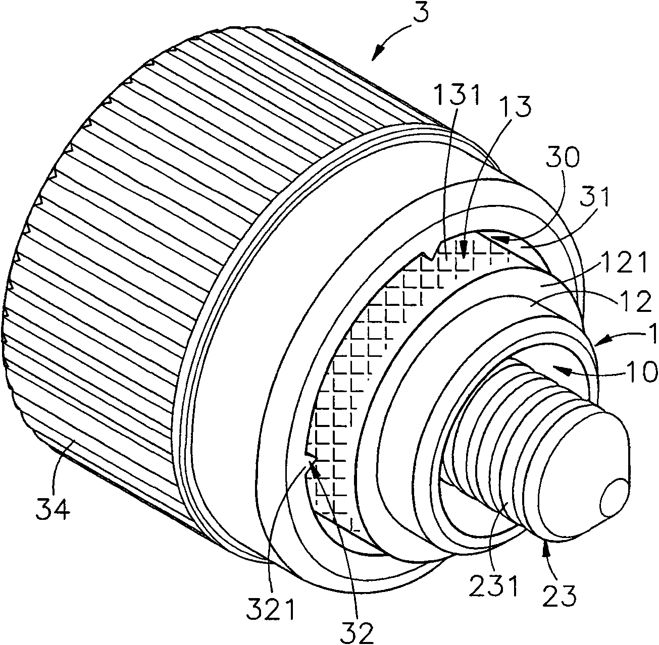
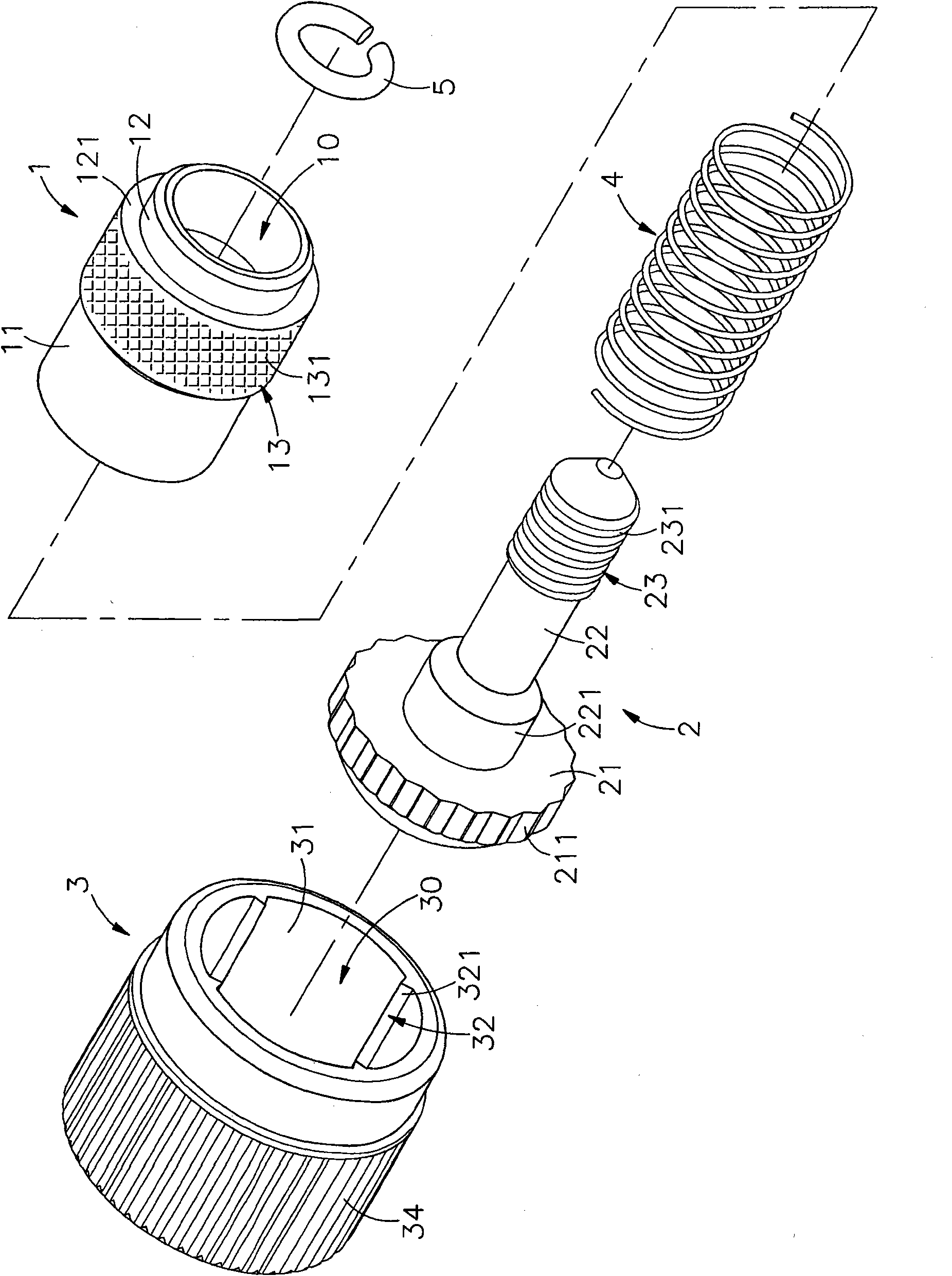
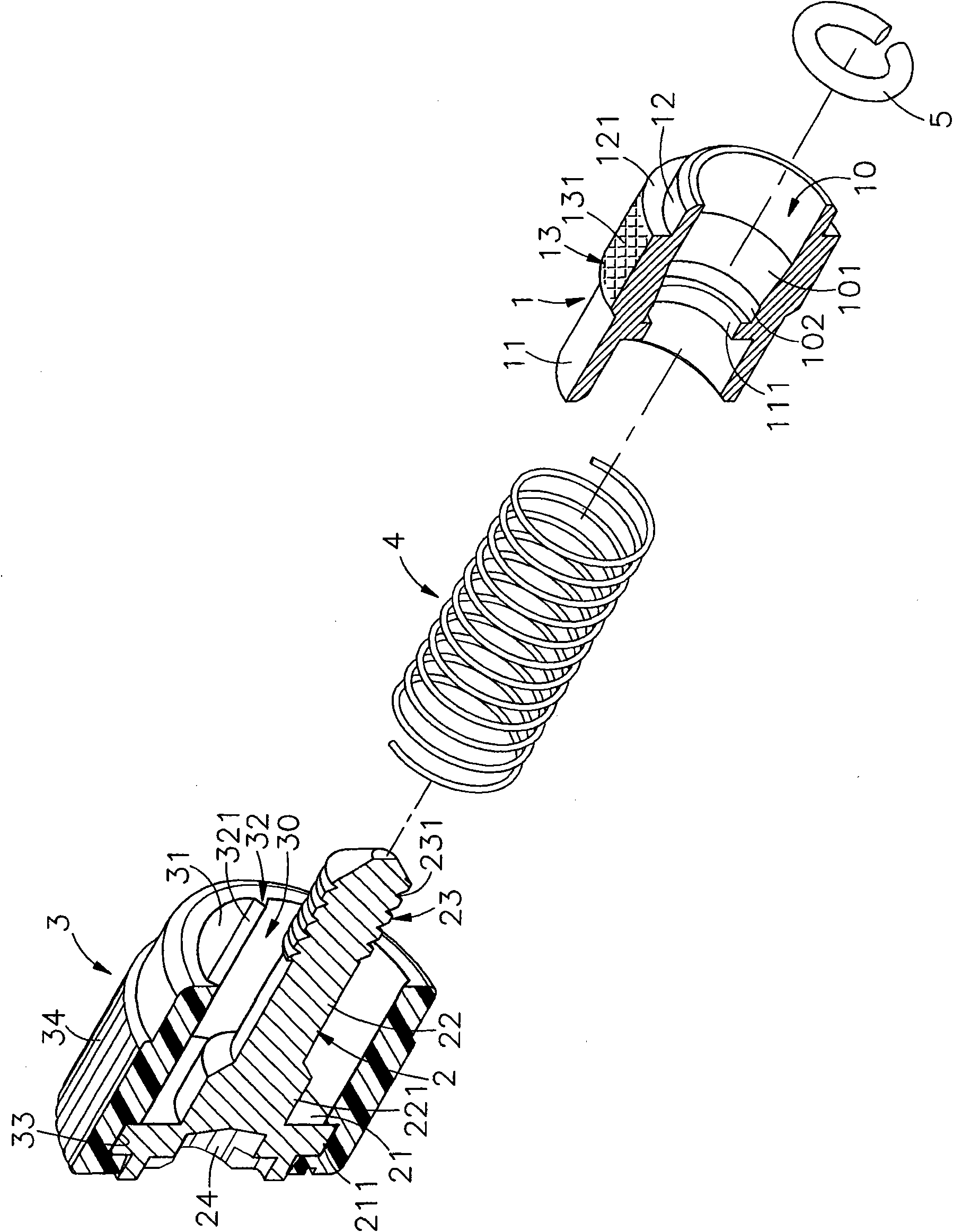
[0023] see figure 1 , figure 2 , image 3 As shown, they are respectively the three-dimensional appearance diagram, the three-dimensional exploded view and the three-dimensional cross-sectional view before assembly of the present invention. It can be clearly seen from the figure that the present invention includes a docking sleeve 1, a locking element 2, an outer sleeve 3, and a spring 4 and the stop ring body 5, so the main components and features of this case are described in detail as follows, wherein:

[0024] The docking sleeve 1 is a hollow pipe body 11, in which a fitting space 10 is formed in the hollow interior, and a ring protrusion 111 with a ...


PUM


Abstract

The invention provides a fixing device. In the fixing device, a combining part is formed at the front edge of a butt joint sleeve, and the periphery at the outer side behind the combining part is provided with a friction part; a locking element is an outer sleeve pipe combined with a plastic rubber or a rubber material at the outer side of a rotating head end, and the butt joint sleeve and a spring are accommodated in the outer sleeve pipe; an interference part is arranged on the inner side surface of a front opening of the outer sleeve pipe, and the interference part of the outer sleeve pipe and the friction part of the butt joint sleeve are aligned and pressed to form preset positioning; the outer sleeve pipe is temporarily pressed and connected to the butt joint sleeve so as to be convenient for an automatic machine to take up the outer sleeve; the combining part is aligned and tightened into a joint hole of a first plate and welded into a whole; then the outer sleeve pipe is held and rotated to ensure that the interference part forms interference and abrasion with the friction part on the butt joint sleeve to form a separation state, thus a movable opposite locking state can be formed through the butt joint sleeve, a locking element and a stopping ring body capable of preventing coming off; and the effects of being convenient for volume production of taking pieces, improving the manufacturing quality and the yield rate and reducing the production cost are achieved.

Description

technical field [0001] The invention provides a fixing device, especially a plastic injection molding of a locking element with an outer casing, and the interference part at the inner wall of the outer casing is used as a preset position with the friction part of the docking sleeve, and is formed after interference and wear Separation, and has a fixture that facilitates mass production and improves manufacturing quality and yield. Background technique [0002] When combining general panels (board-to-board), in order to utilize set screws equipped with knobs, collars and screws to be locked, the screws and collars are fixed on the first panel, and the knobs are rotated to make the screws Locked into the second panel to form a preset position, and then use hand tools to lock the screws, so that the first panel and the second panel are locked and fixed as one, and can be used in machine tools or other board-to-board Used on connected panels. [0003] Furthermore, there are al...

Claims


Application Information

Patent Timeline
Patent Type & Authority Applications(China)
IPC IPC(8): F16B35/00F16B5/02
Inventor 王国仲
Owner 王国仲
Why Eureka
Try Eureka