Manufacture method of composite screw

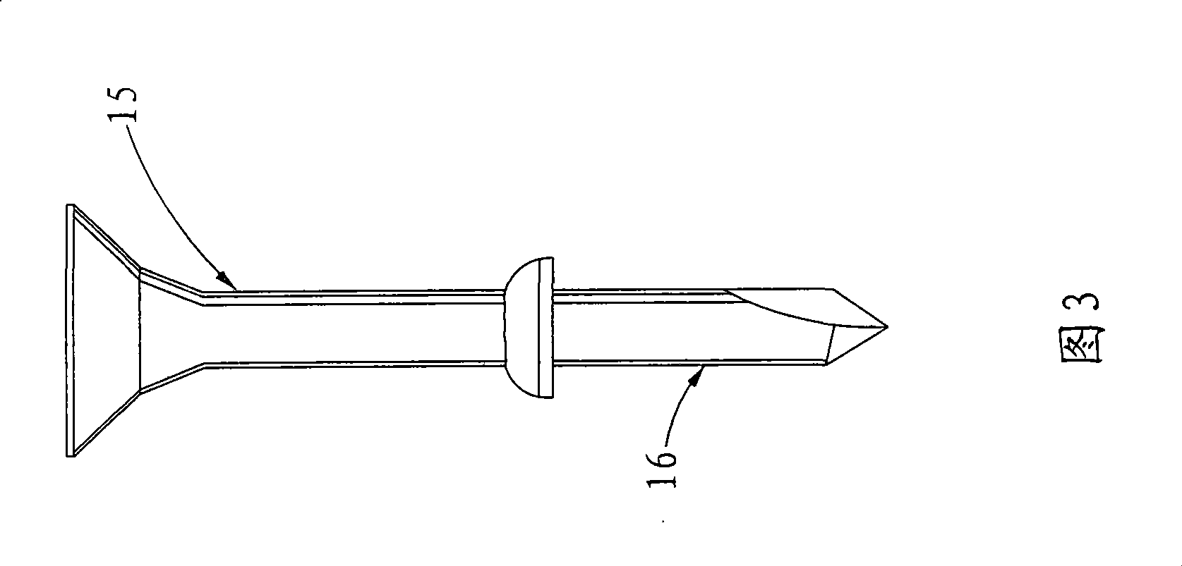
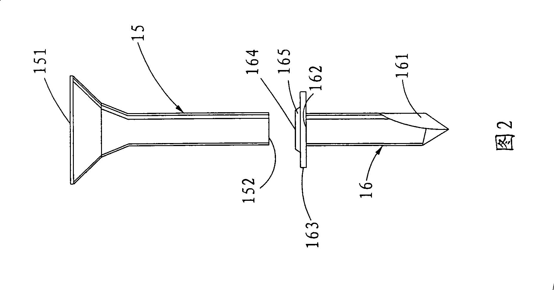
A technology of composite material and manufacturing method, which is applied in the field of composite material screw manufacturing, and can solve problems such as skewing, partial air cannot be released smoothly, and affecting the joint strength of the rod body 15 and the drill tail 16, etc.

Inactive Publication Date: 2009-02-11
TOP WELL TECH CORP
View PDF0 Cites 6 Cited by
  • Summary
  • Abstract
  • Description
  • Claims
  • Application Information

AI Technical Summary

Problems solved by technology

[0005] 1. When the rod body 15 and the drill tail 16 are welded, the welding end 152 and the bump 165 are frictionally engaged with each other. In view of the fact that the welding end 152 and the flat surface 164 of the bump 165 are rotated against each other during the welding process, It is easy to make part of the air unable to be released smoothly during welding, resulting in that after the rod body 15 and the drill tail 16 are welded, the welded part is likely to accumulate pores due to air being covered, which affects the joint strength of the rod body 15 and the drill tail 16
[0006] 2. Continuing from the above, in view of the fact that the two planes of the welding end 152 and the engaging piece 163 are parallel, and the friction welding process must utilize high voltage cooperation, it is not easy to make the rod body 15 and the drill tail 16 Alignment with each other will cause irreparable skew after welding, affecting manufacturing quality and yield, and it is worth improving

Method used


Image

  • Manufacture method of composite screw
  • Manufacture method of composite screw
  • Manufacture method of composite screw

Examples


Embodiment Construction

[0031] The aforementioned and other technical contents, features and effects of the present invention will be described in detail below with reference to the drawings and preferred embodiments.

[0032] Before the present invention is described in detail, it should be noted that in the following description, similar elements are denoted by the same reference numerals.

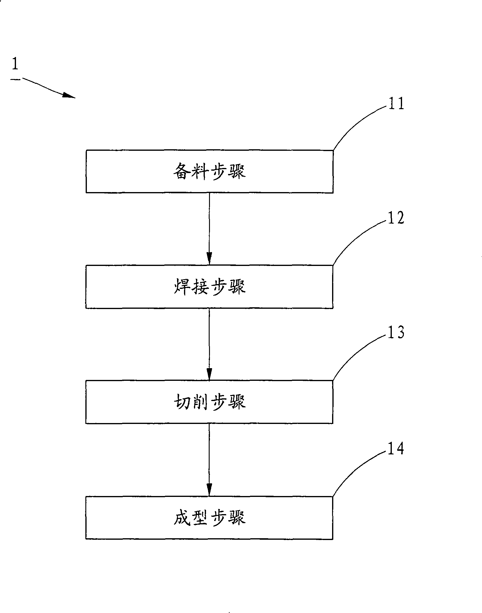
[0033] refer to Figure 6 , the first preferred embodiment of the present invention, the manufacturing method 5 of the composite material screw mainly includes a material preparation step 51, a welding step 52, a cutting step 53 and a forming step 54 and other steps.

[0034] Cooperate with reference Figure 7 , the material preparation step 51 divides the base metal molding of different materials into a rod body 7 and a drill tail 8; wherein, the rod body 7 is made of stainless steel in this embodiment, and one end of the rod body 7 is formed into a screw head 71, and opposite to the other end of the screw h...


PUM


Abstract

The invention relates to a method for producing a screw of composite material. The method comprises the steps of material preparation, welding, cutting and shaping in sequence, wherein, in the material preparation step, two different materials are divided into a rod body part and a drilling tail part; a welding part is formed on the rod body part, and a taper body is formed on the drilling tail part. Through the taper surface formed on the taper body, not only air can be smoothly exhausted when the rod body part is welded with the drilling tail part (namely, the welding step), so as to avoid air covering in the welding process, and ensure that pores can not appear at the welding positions, but also the composite blank can not be deflected after welding; finally, through the cutting of residual material in the cutting step, and shaping operations of screw thread rolling and the like, the screw of the composite material can be shaped, therefore, the quality of the screw of the composite material can truly be improved through the method.

Description

technical field [0001] The invention relates to a method for manufacturing a composite material screw. Background technique [0002] refer to figure 1 And Fig. 2, the conventional composite material screw manufacturing method 1, which includes material preparation step 11, welding step 12, cutting step 13 and forming step 14, etc.; wherein, the material preparation step 11 is to distinguish and form two base materials of different materials It is a rod body portion 15 and a drill tail portion 16, and one end of the rod body portion 15 is formed into a screw head 151, and a welding end 152 opposite to the direction of the screw head 151 is formed; again, one end of the drill tail portion 16 is formed as A drill tail end 161, and the opposite direction of the drill tail end 161 is provided with a joint end 162, and a joint piece 163 combined with the welding end 152 protrudes from the joint end 162, and a joint piece 163 is protruded on the joint piece 163 There is a bump 16...

Claims


Application Information

Patent Timeline
Patent Type & Authority Applications(China)
IPC IPC(8): B23P15/00
Inventor 谢抑霖
Owner TOP WELL TECH CORP
Why Eureka
Try Eureka