
Rotary cutting valve

A technology of rotary cutting valves and discs, which is applied in the direction of sliding valves, valve details, valve devices, etc., and can solve problems such as sedimentation and scaling

Inactive Publication Date: 2011-01-12
江苏江恒阀业有限公司
View PDF0 Cites 6 Cited by
  • Summary
  • Abstract
  • Description
  • Claims
  • Application Information

AI Technical Summary

Problems solved by technology

[0003] In order to overcome the problem that the existing ball valves easily cause sedimentation and scaling in the inner cavity of the valve, the present invention provides a valve that prevents scaling and sedimentation in the valve body, effectively keeps the channel of the valve body unblocked, and thus ensures the normal operation of the pipeline. At the same time, it also has the same rapid opening and closing characteristics as the ball valve.

Method used


Image

  • Rotary cutting valve
  • Rotary cutting valve
  • Rotary cutting valve

Examples


Embodiment Construction

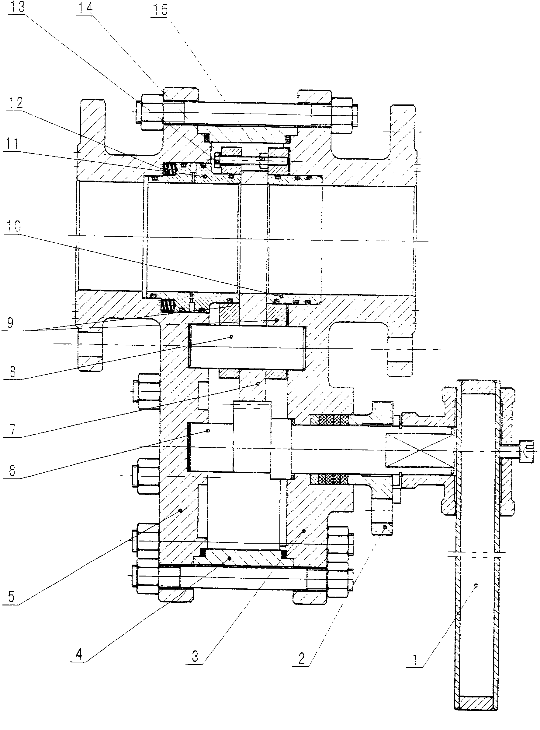
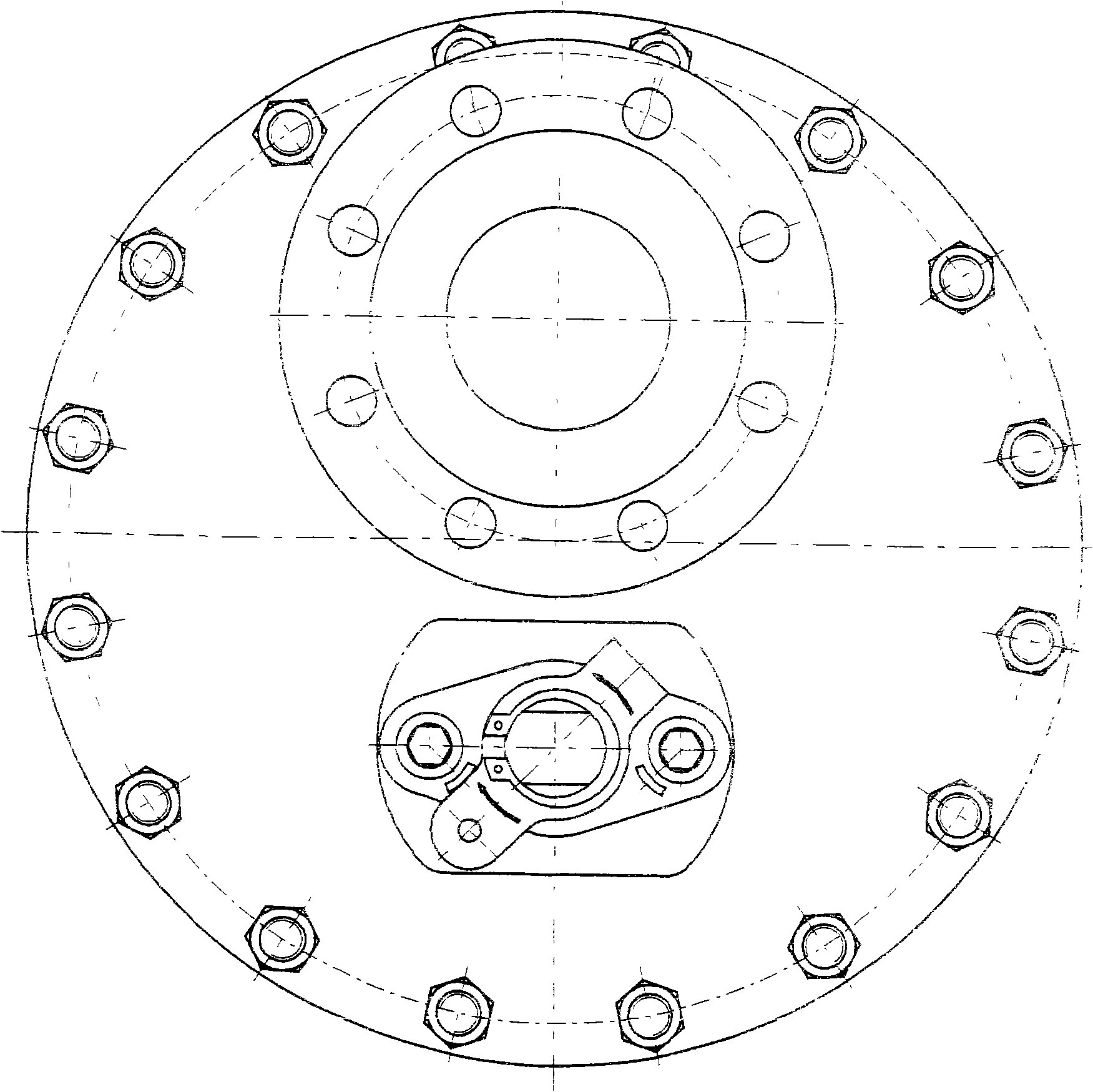
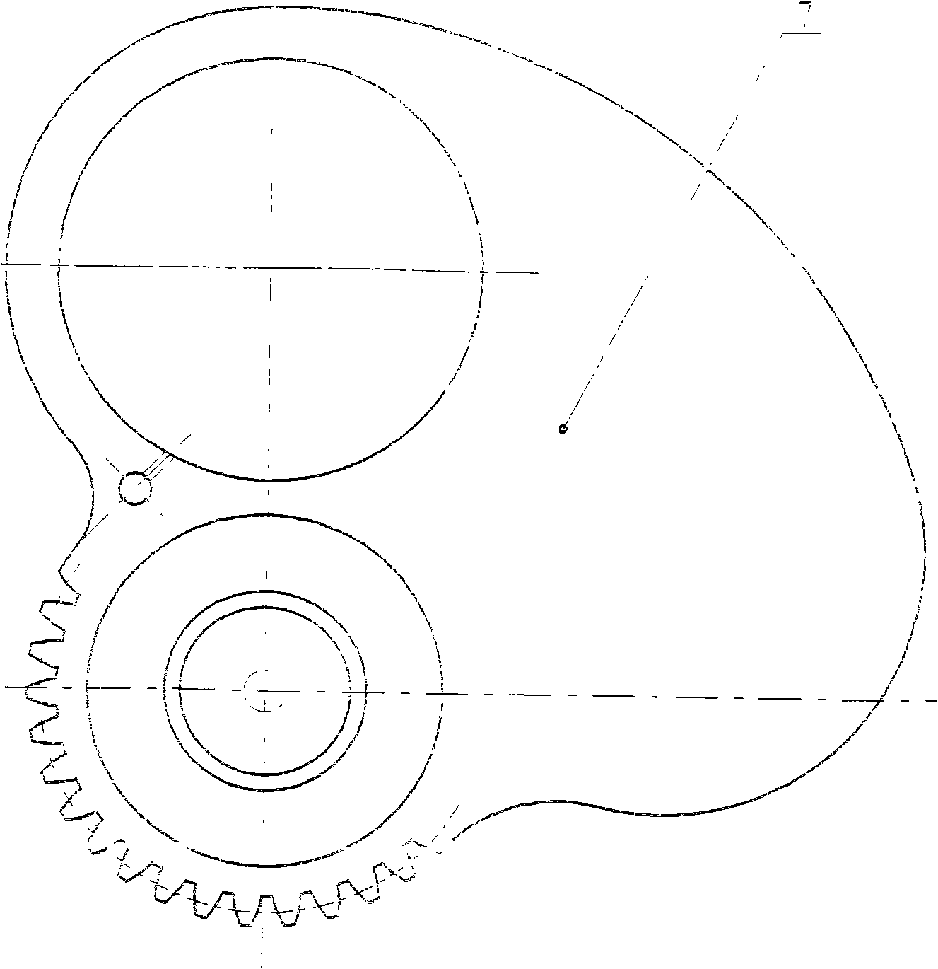
[0014] As shown in the figure, the right valve body 3, the intermediate body 4, and the left valve body 5 form a shell. The handle 1, the packing gland 2, the right valve body 3, the left valve body 5, and the valve stem 6 are connected, and the valve stem 6 is inserted in the left In the positioning hole of the valve body 5, the fixed shaft 8 passes through the splint 9 and the valve disc 7 on both sides, and the two ends are inserted into the positioning holes of the right valve body 3 and the left valve body 5. The right valve body 3, the right valve seat 10, Valve disc 7, left valve seat 11, cylindrical compression spring 12, left valve body 5 are connected, hexagon head bolt 13, butterfly spring 14, hexagon nut 15 are used as fasteners, connecting splint 9, valve disc 7, right valve seat 10. There is an "O" seal between the outer circle of the left valve seat 11 and the right valve body 3, the left valve body 5 and the clamping plate 9. The valve stem 6, the valve disc 7 ar...


PUM


Abstract

The invention discloses a rotary cutting valve. A left valve body, an intermediate body and a right valve body form a housing; a handle, a valve rod, a gland cover, the right valve body and the left valve body are connected; the valve rod is inserted into the positioning hole of the left valve body; a fixing shaft passes through a splint and a valve clack on the two sides; the two ends of the fixing shaft are inserted into the positioning holes of the left and right valve bodies; the right valve body, a right valve seat, the valve clack, a left valve seat, a cylindrical compression spring and the left valve body are connected; the splint and the valve clack are connected; a hexagonal bolt, a belleville spring and a hexagonal nut serve as fasteners which is a structure floating with the position of the valve clack; the outer circles of the left and right valve seats and the left and right valve bodies and the splint are sealed by O-shaped sealing rings; the valve rod and the valve clack transversely rotate around a gear pair; the splint is a semicircular plate of which the upper part is provided with a medium channel hole, the lower part is provided with a fixing shaft hole and the two sides are provided with blind plates; the valve clack is a sector plate of which the upper part is provided with a medium channel hole, the right side is provided with a blind plate and the lower part is provided with a fixing shaft hole; the outer side of the shaft hole is provided with a semicircular gear; and the valve rod is also provided with a semicircular gear. The valve can ensure that deposit or scale is not generated in the inner cavity.

Description

Technical field [0001] The invention relates to a valve capable of eliminating scale and precipitation in a valve body cavity. Background technique [0002] The valve with the ball as the closing part is called the ball valve. Because of its simple and convenient operation, it is widely used in industrial production pipelines such as chemical industry, petroleum, metallurgy, electric power, energy, etc. It only needs to rotate 90° by controlling the rotation of the ball. The valve can be opened and closed within a few seconds. However, when the ball is closed or opened, the medium must enter the inner cavity of the valve body. In the state of two-phase flow, the medium often precipitates and scales in the inner cavity of the valve, causing the ball to fail to rotate, which leads to the failure of the entire valve. , Affecting the normal operation of the pipeline. Summary of the invention [0003] In order to overcome the problem that the existing ball valve easily causes precipi...

Claims


Application Information

Patent Timeline
Patent Type & Authority Applications(China)
IPC IPC(8): F16K3/06F16K31/60
Inventor 吴万江
Owner 江苏江恒阀业有限公司
Learn More