
Automatic constant-temperature water mixing valve

A constant temperature mixing valve, automatic technology, applied in valve details, multi-way valves, valve devices, etc., can solve the problems of backflow of cold water into hot water, low response sensitivity, high water resistance, etc.

Inactive Publication Date: 2011-01-12
常州市华鹏机械电器制造有限公司
View PDF5 Cites 20 Cited by
  • Summary
  • Abstract
  • Description
  • Claims
  • Application Information

AI Technical Summary

Problems solved by technology

The automatic temperature control mixing water valve of this structure adjusts the ratio of cold and hot water inlet through the movement of the piston in the cylindrical annular water flow sleeve, which has the disadvantages of high water resistance and uneven mixing of cold and hot water; and after the hot water enters the valve cavity The cold water flows out along the axis to the mixing outlet, and the cold water enters the mixing chamber along the vertical axis. The fluid form is that hot water drives the cold water to flow out. In ordinary households, the pressure of hot water is generally lower than that of cold water, which may easily cause backflow of cold water into hot water; It has the disadvantages of complex structure and low reaction sensitivity

Method used


Image

  • Automatic constant-temperature water mixing valve
  • Automatic constant-temperature water mixing valve
  • Automatic constant-temperature water mixing valve

Examples


Embodiment Construction

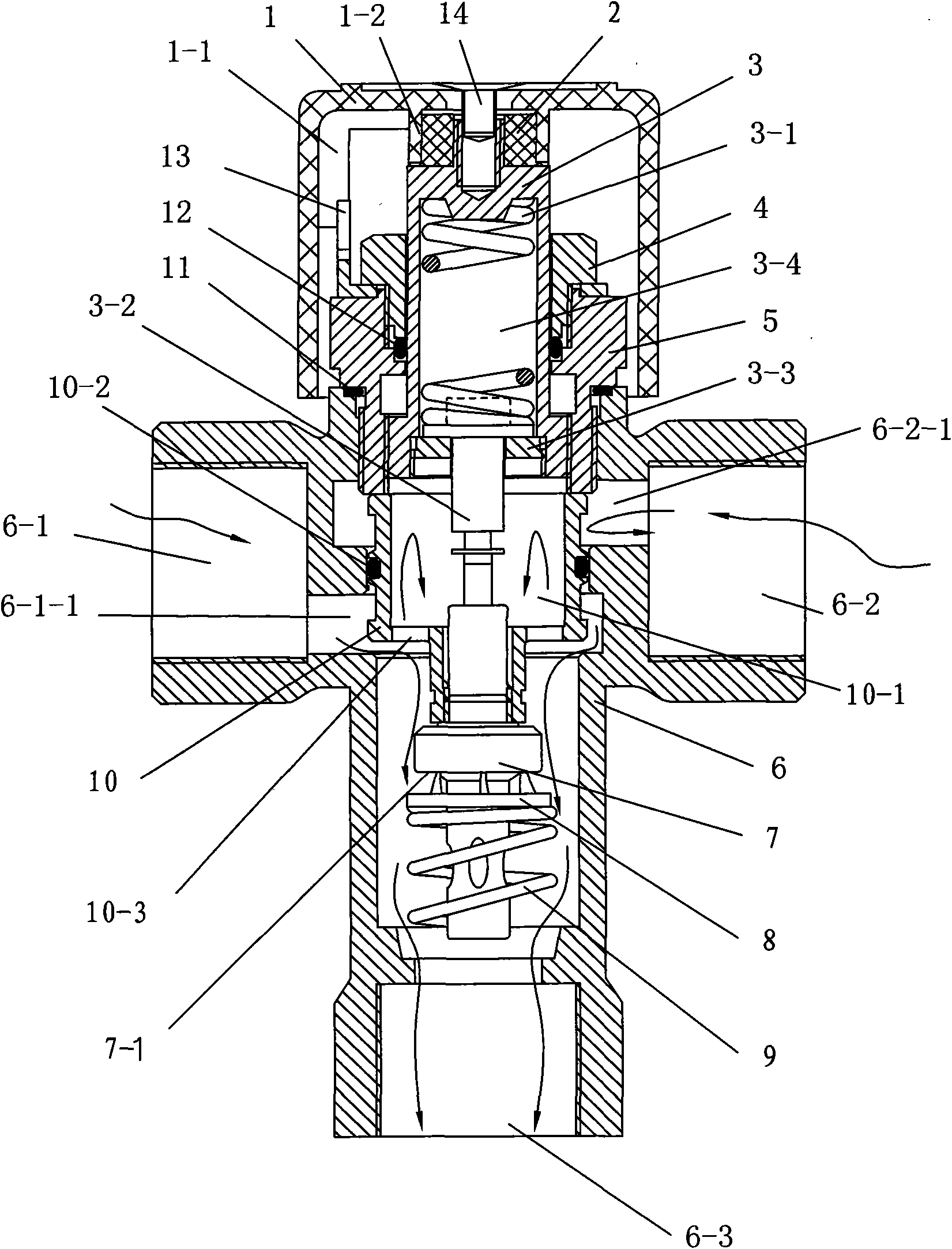
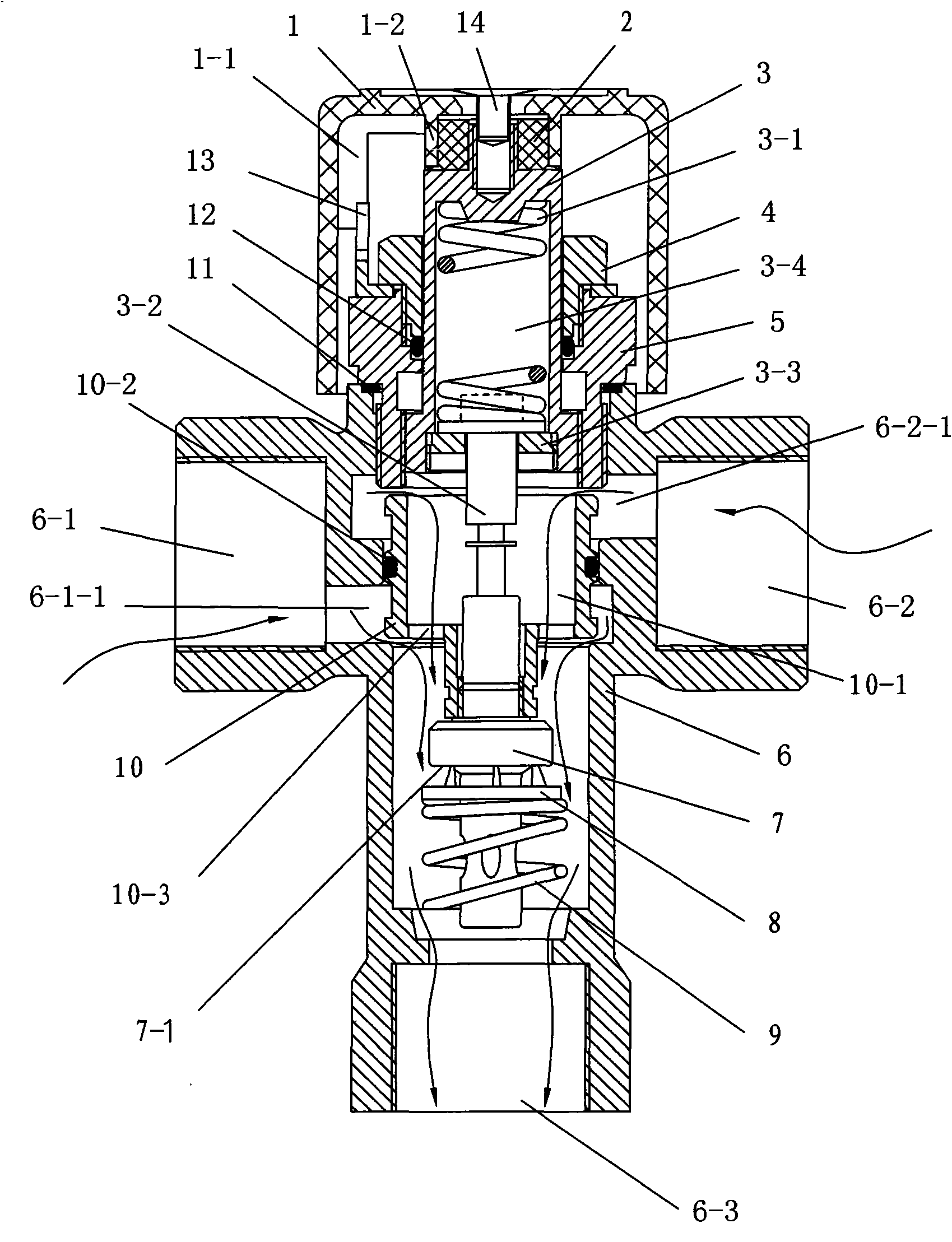
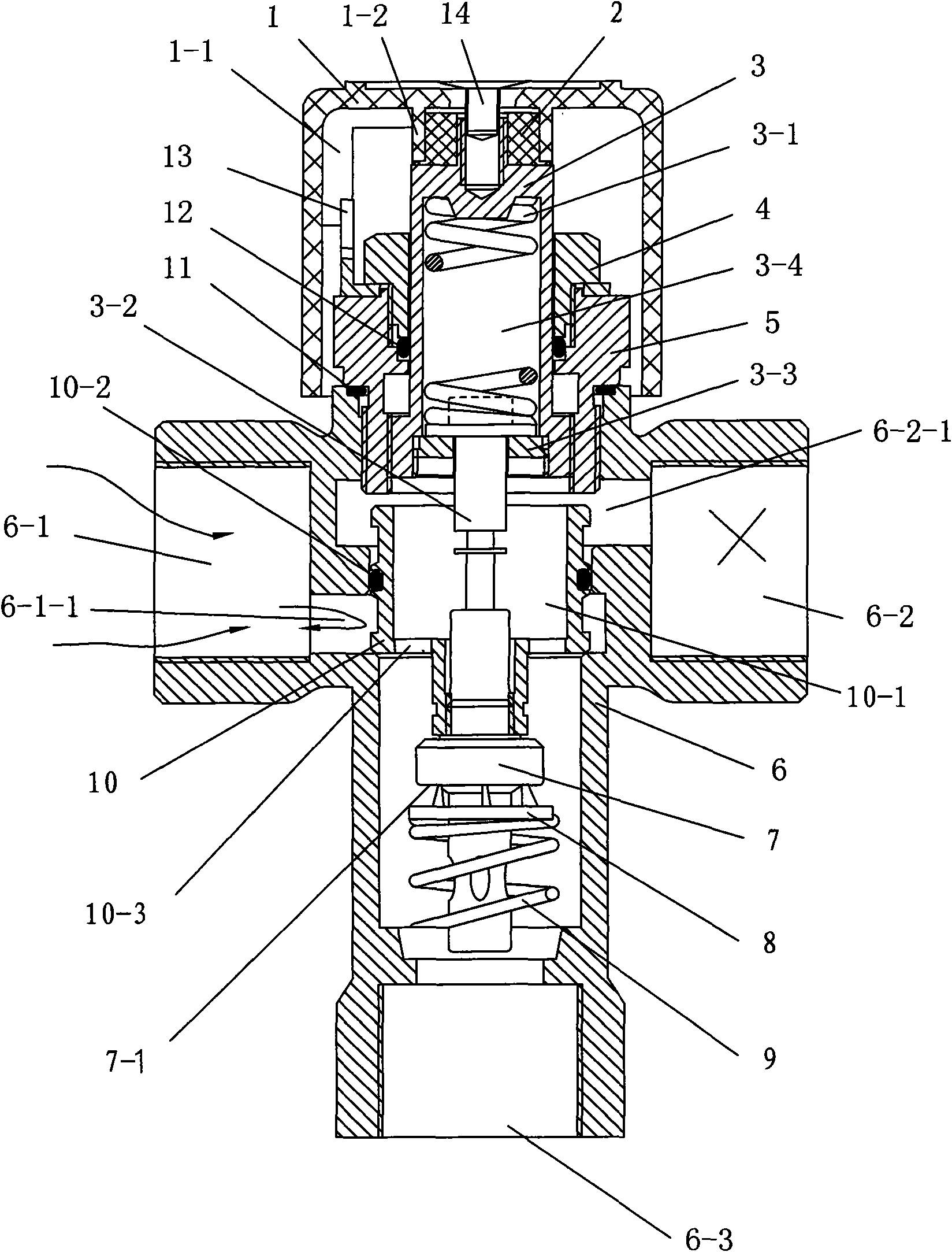
[0030] Such as figure 1 , 2 , 3, 4, 7, 10, 11, an automatic thermostatic water mixing valve, including a valve body 6, a temperature sensing rod 7, a working spring 9, an adjustment screw 3 and a temperature adjustment knob 1, wherein the valve body 6 is provided with There are hot water inlet 6-1, cold water inlet 6-2 and mixed water outlet 6-3, the temperature sensing rod 7 and the working spring 9 are set in the valve body 6, the temperature adjustment knob 1 is connected with the adjustment screw rod 3, The valve body 6 is provided with a valve plug 10, and the middle part of the valve plug 10 is movably matched with the inner wall of the valve body 6. The upper part of the valve plug 10 is located at the inner end 6-2-1 of the cold water inlet 6-2, and the valve plug The lower part of 10 is located at the inner end 6-1-1 of the hot water inlet 6-1, the valve plug 10 has an axial through hole 10-3, and the axial through hole 10-3 leads to the mixed water outlet 6-3 , the...


PUM


Abstract

The invention discloses an automatic constant-temperature water mixing valve. The water mixing valve comprises a valve body, a temperature sensing rod, a work spring, an adjusting screw rod and a tempering knob, wherein the valve body is provided with a hot water inlet, a cold water inlet and a mixed water outlet; the tempering knob is connected with the adjusting screw rod; a valve plug is arranged in the valve body; the middle part of the valve plug is movably matched with the inner wall of the valve body; the upper part of the valve plug is positioned at the inner end of the cold water inlet; the lower part of the valve plug is positioned at the inner end of the hot water inlet; the valve plug is provided with an axial through hole; the temperature sensing rod is fixedly connected to the lower part of the valve plug; the upper part of the temperature sensing rod is positioned in the cavity of the valve plug; a water mixing ring and the work spring are sleeved on the lower part of the temperature sensing rod; the lower end of the work spring is pressed against the inner wall of the valve body; the top rod of the adjusting strew rod can be pressed against the upper end of the temperature sensing rod; the valve body is in threaded connection with a large end cover; the adjusting strew rod is in threaded connection with the large end cover; the large end cover is also in threaded connection with a small end cover; and a buffer spring is arranged in the blind hole of the adjusting screw rod. The water mixing valve has the advantages of low water resistance and high reaction sensitivity.

Description

technical field [0001] The invention relates to a water mixing valve, in particular to an automatic thermostatic water mixing valve matched with a hot water device. Background technique [0002] Nowadays, the hot water devices widely used in the family are equipped with various faucets, water mixing valves and other components. In actual use, since there are multiple faucets in the house, water may be used at the same time. The water pressure of the water mixing valve in the water mixing valve changes, causing the water temperature of the mixed water to be affected and fluctuating; or when the water temperature of the hot water source changes, the temperature of the mixed water coming out of the water mixing valve will fluctuate, so it needs to be readjusted The water mixing valve is used to correct the water temperature. This process is often repeated many times, resulting in a waste of water resources. Chinese patent document CN2883824 discloses an automatic temperature c...

Claims


Application Information

Patent Timeline
IPC IPC(8): F16K11/044F16K31/70F16K31/60F16K31/53F16K37/00
Inventor 王红宽
Owner 常州市华鹏机械电器制造有限公司
Learn More