LED (Light Emitting Diode) optical lens

An optical lens and body technology, applied in the field of LED optical lenses, can solve the problems of high cost, difficult to manufacture, and complex structure, and achieve the effects of low cost, reduced discomfort, and controlled glare

Inactive Publication Date: 2011-01-12
CHONGQING SILIAN OPTOELECTRONICS SCI & TECH
View PDF3 Cites 0 Cited by
  • Summary
  • Abstract
  • Description
  • Claims
  • Application Information

AI Technical Summary

Problems solved by technology

For this reason, a LED optical lens is developed on the light-emitting side of the LED, so that the light emitted by the LED can be refracted through the offset of the LED lens, so that the scattered light can be guided into a uniform irradiation surface. At present, various forms of LED lenses have come into the market. However, various forms of LED lenses still have the problems of complex structure, difficult manufacture and high cost.

Method used


Image

  • LED (Light Emitting Diode) optical lens
  • LED (Light Emitting Diode) optical lens
  • LED (Light Emitting Diode) optical lens

Examples


Embodiment Construction

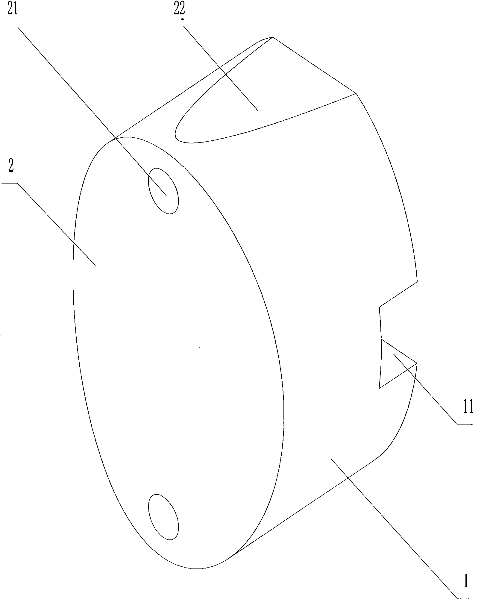
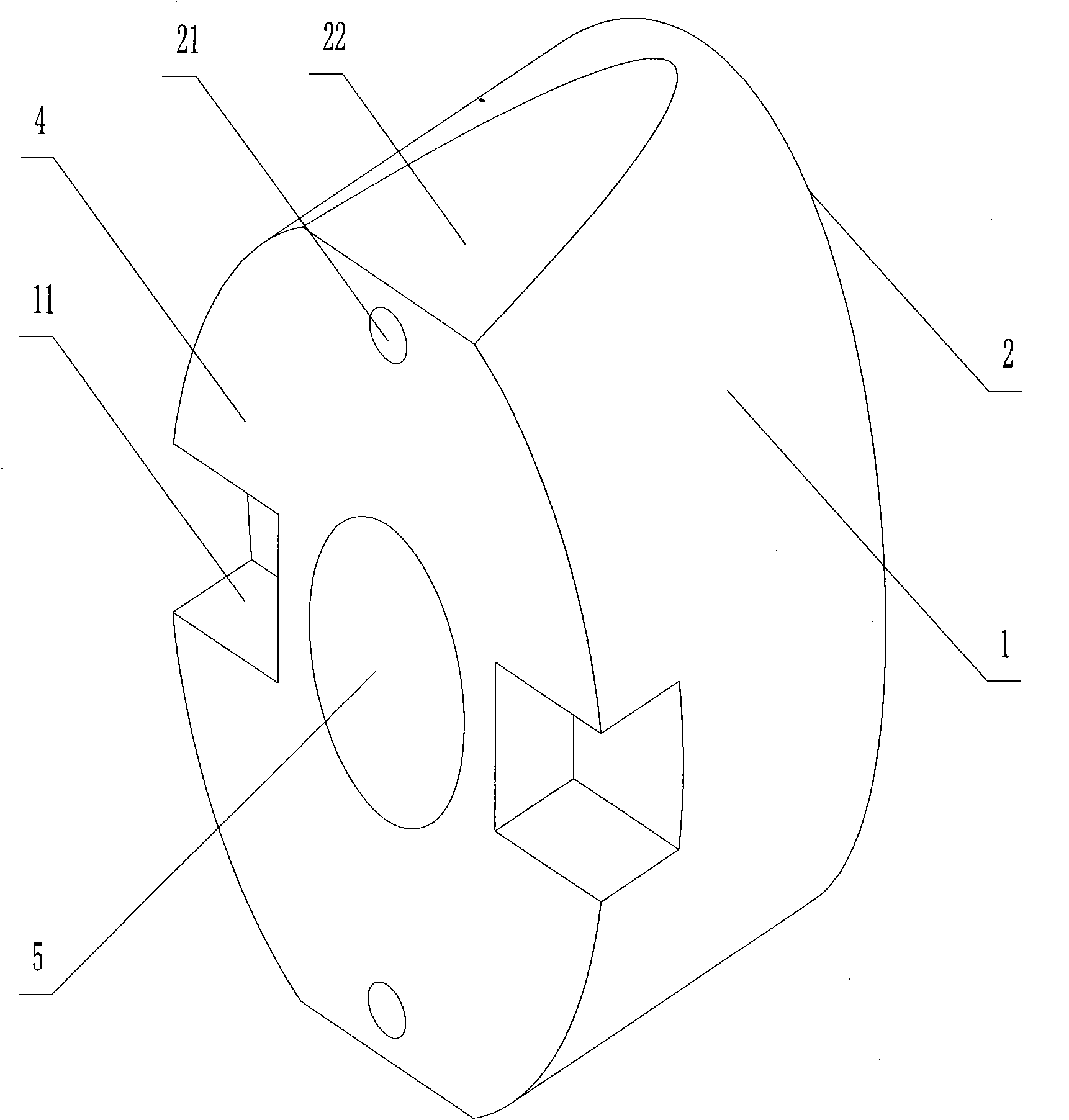
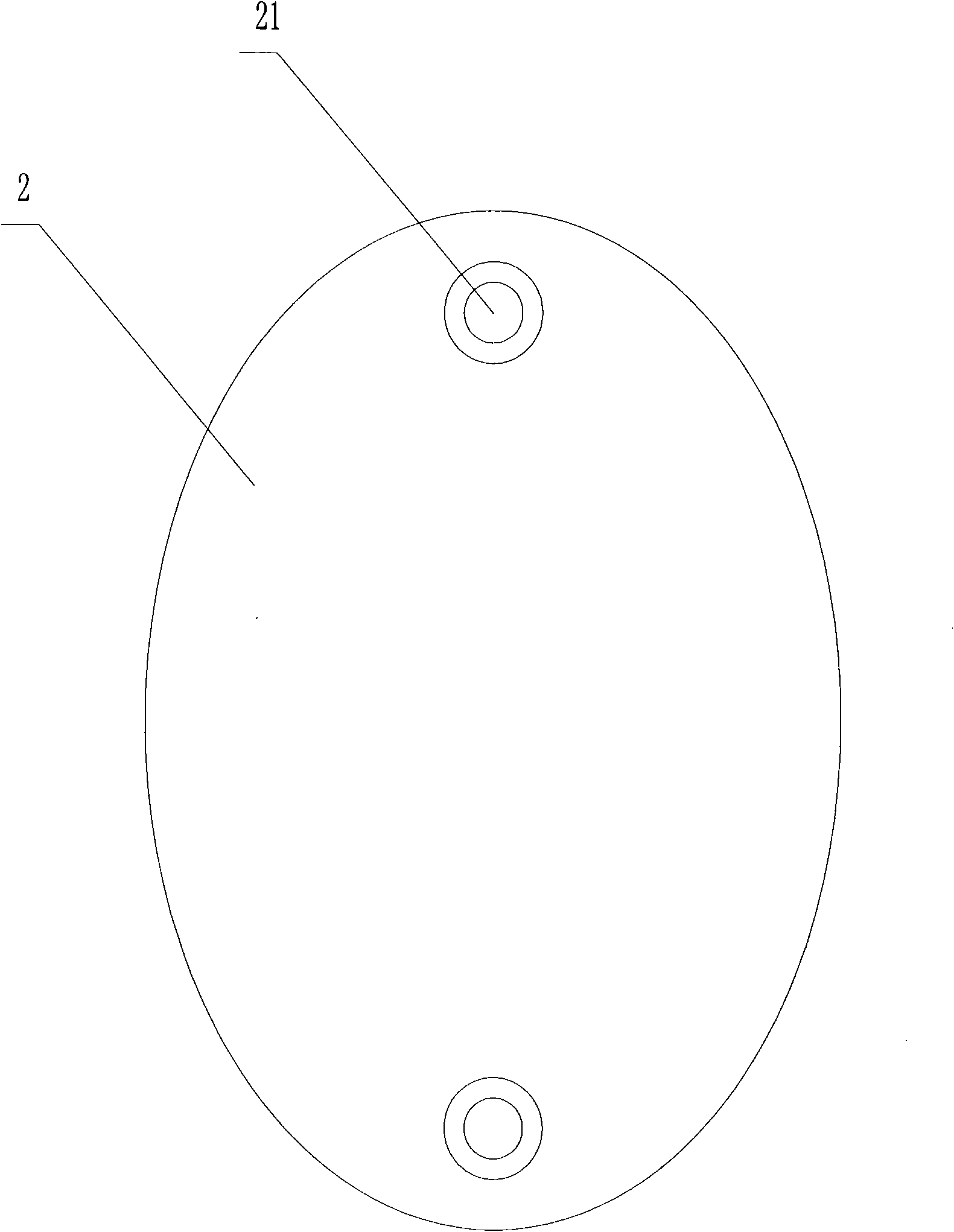
[0019] Such as Figure 1 to Figure 6 As shown, the LED optical lens, the entire light-transmitting body 1 is embedded in the lamp hole of the LED lighting handrail. The light-transmitting body 1 is generally a cylinder with an elliptical cross-section. The exit surface 2 is consistent with the surface arc surface of the lighting handrail. The exit surface 2 is an elliptical surface with a protruding middle and a smooth transition to the edge, and the surface has been frosted. The internal structure and structure cannot be seen from the exit surface 2. part. The bottom 4 of the light-transmitting body 1 is a plane, and the middle part of the bottom 4 has a groove 5 for accommodating LED lamp beads. The inner surface of the groove 5 is a hemispherical total incidence surface. Two rectangular notches 11 are formed at both ends of the ellipse's short axis direction on the bottom 4, and the rectangular notches 11 are used to accommodate the solder joints on the substrate to avoid ...


PUM


Abstract

The invention relates to an LED optical lens comprising a cylindrical light transmission body with an elliptic section, wherein the bottom of the cylindrical light transmission body is provided with a lamp hole which is used for placing an LED in, a fully reflecting surface is arranged around the lamp hole, the front end of the cylindrical light transmission body is provided with an emitting surface which is matched with a cambered surface of a handle pipe, and the emitting surface is an elliptic curved surface with a projected middle which is smoothly changed to an edge. The LED optical lens evenly irradiates light on the ground by optical processing, eliminates an adverse condition of decentralized light divergence, greatly increases optical utilization rate, effectively controls glare at the same time, greatly reduces the discomfort of pedestrians, achieves illuminating effect of only seeing light without a lamp and has simple structure and lower cost.

Description

technical field [0001] The invention relates to an LED optical lens, in particular to a novel lens applied to an LED lighting handrail. Background technique [0002] It is the current trend to develop LED lighting fixtures by utilizing the characteristics of low driving voltage, fast response and low power consumption of LEDs to replace traditional lighting fixtures. [0003] Due to the luminous characteristics of the LED, although the light is directional, the light it emits is a cobblestone light distribution, so that the effective light projected forward by the LED is a fixed luminous angle, that is, the light emitted by the LED still has the disadvantage of being reduced due to scattering. To improve its illuminance and effect, direct processing is very difficult. As an LED lighting handrail, there are strict regulations on the power of LEDs. There are strict requirements on illumination and strict glare control in public places. For this reason, a LED optical lens is ...

Claims


Application Information

Patent Timeline
Patent Type & Authority Applications(China)
IPC IPC(8): F21V5/04F21Y101/02
Inventor 胡栋
Owner CHONGQING SILIAN OPTOELECTRONICS SCI & TECH
Why Eureka
Try Eureka