Rapid calibration method of line-structured light vision sensor based on space plane restriction

A technology of line structured light and calibration method, applied in the field of online structured light vision measurement system, can solve problems such as being unsuitable for on-site calibration, requiring high three-dimensional processing accuracy of targets, and limiting calibration accuracy.

Inactive Publication Date: 2012-04-25
TIANJIN UNIV
View PDF4 Cites 2 Cited by
  • Summary
  • Abstract
  • Description
  • Claims
  • Application Information

AI Technical Summary

Problems solved by technology

At present, the main commonly used calibration methods are: wire drawing method and sawtooth target method. The calibration points obtained by these two calibration methods often have low accuracy and a small number, which limits the improvement of calibration accuracy.
There is another calibration method based on the mechanical adjustment method of the target surface. The realization of this method requires a precision mobile platform, which is expensive, inconvenient to operate, and time-consuming to calibrate. Although high-precision calibration points can be obtained through this method, it is not suitable for On-site calibration
Another calibration method is to use the cross-ratio invariance to extract the fixed point of the structural cursor. This method can obtain high-precision calibration points through high-precision three-dimensional calibration targets, and is suitable for on-site measurement. However, the three-dimensional processing accuracy of the target requires higher

Method used


Image

  • Rapid calibration method of line-structured light vision sensor based on space plane restriction
  • Rapid calibration method of line-structured light vision sensor based on space plane restriction
  • Rapid calibration method of line-structured light vision sensor based on space plane restriction

Examples


Embodiment Construction

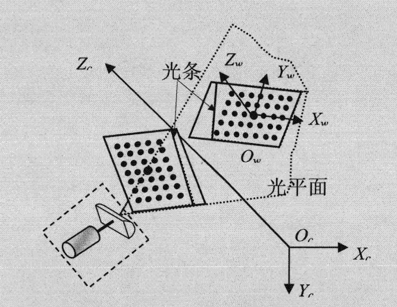
[0036] The implementation process of the present invention will be described in detail below in conjunction with the accompanying drawings and a specific embodiment.

[0037] like Figure 4 As shown, the present invention is based on the calibration method of the line structured light visual measurement sensor constrained by the spatial plane, comprising the following steps:

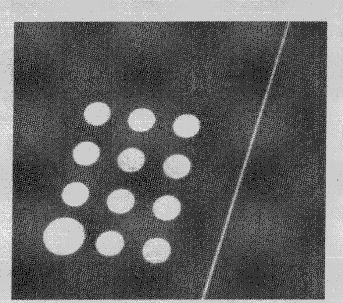
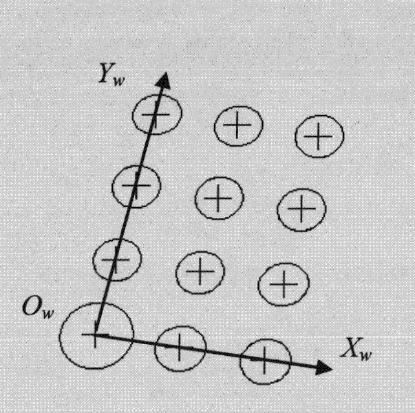
[0038] First, the acquired image of the designed two-dimensional planar target is as follows: Picture 1-1 and Figure 1-2 As shown, there are white feature circles arranged in a matrix on the target plane, the distance D between the centers of adjacent feature circles is selected as 10 mm, the spacing accuracy is (0.01 mm), and the number m of feature circles is 12 to 35. In this embodiment, m= 12. The determination of the values ​​of m and D is mainly determined according to the size of the field of view of the specific camera and the range of the depth of field. The specific determination of the valu...


PUM


Abstract

The invention discloses a calibration method of a line-structured light vision measuring sensor based on the space plane restriction, comprising the following calibrating steps: placing a two-dimensional planar target in a camera field range; collecting a group of images of multiple characteristic circles at the different positions on a two-dimensional target panel; determining the target topological relation; and synchronously completing the internal parameter calibration and the light planar calibration of a camera. In the process of the light planar calibration, substantial quantity of line-structured light planar three-dimensional points can be easily extracted by utilizing a camera imaging model and the restraining provided by the space plane formed by each position target; and planar fitting is carried out on the three-dimensional point set based on a principal element analytical method, so as to obtain an equation of the light plane in the coordinate system. The calibration method of the invention has simple operation and reliable result, is suitable for field calibration, and can satisfy the requirements of the line-structured light vision high-precision detecting tasks.

Description

technical field [0001] The invention relates to a line structured light vision measurement system, in particular to a fast calibration method for a line structured light vision sensor based on spatial plane constraints. Background technique [0002] Line structured light vision measurement technology is a non-contact active sensing measurement technology, which has the advantages of simple structure, good flexibility, strong anti-interference, rapid measurement, and easy extraction of light strip image information. It has important significance and broad application prospects in high-speed visual measurement, industrial inspection, reverse engineering and other fields. [0003] The calibration of line structured light vision sensor is a key technology in the field of line structured light vision measurement technology. At present, the main commonly used calibration methods are: wire-drawing method and sawtooth target method. The calibration points obtained by these two cali...

Claims


Application Information

Patent Timeline
Patent Type & Authority Patents(China)
IPC IPC(8): G01B11/00
Inventor 刘斌孙长库
Owner TIANJIN UNIV
Why Eureka
Try Eureka