Electric main shaft structure capable of realizing self-examination of thermal extension

A technology of thermal elongation and self-detection, which is applied in the direction of structural connection, electrical components, electromechanical devices, etc., can solve the problems of complex working conditions on site and difficulties in thermal elongation of the main shaft, and achieve the effect of avoiding the thermal elongation of the main shaft

Inactive Publication Date: 2011-01-12
ZHEJIANG UNIV
View PDF2 Cites 7 Cited by
  • Summary
  • Abstract
  • Description
  • Claims
  • Application Information

AI Technical Summary

Problems solved by technology

However, since the speed of the electric spindle usually exceeds 6000r/min during processing, the on-site working conditions during pro

Method used


Image

  • Electric main shaft structure capable of realizing self-examination of thermal extension
  • Electric main shaft structure capable of realizing self-examination of thermal extension

Examples


Embodiment Construction

[0013] The present invention will be further described below in conjunction with drawings and embodiments.

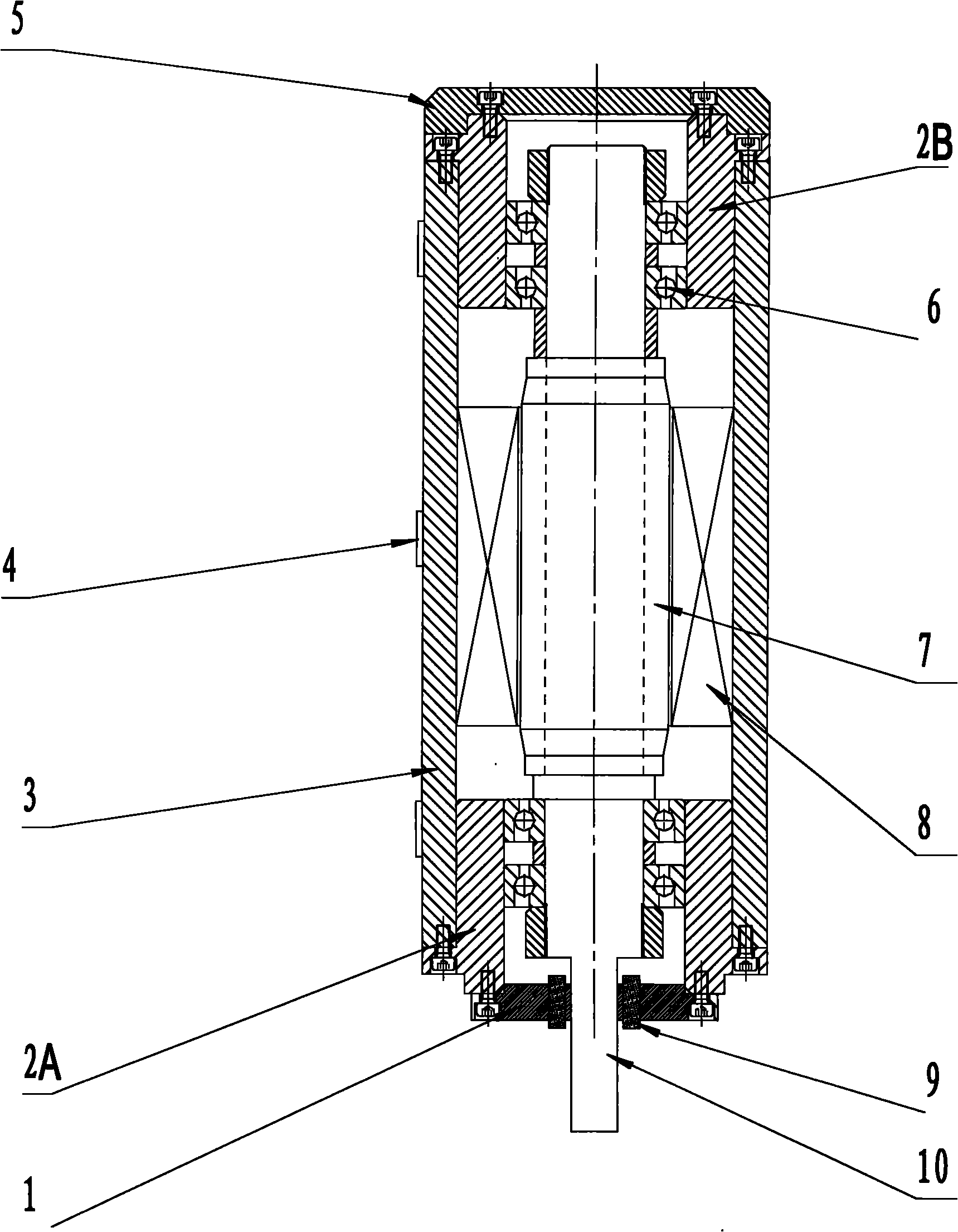
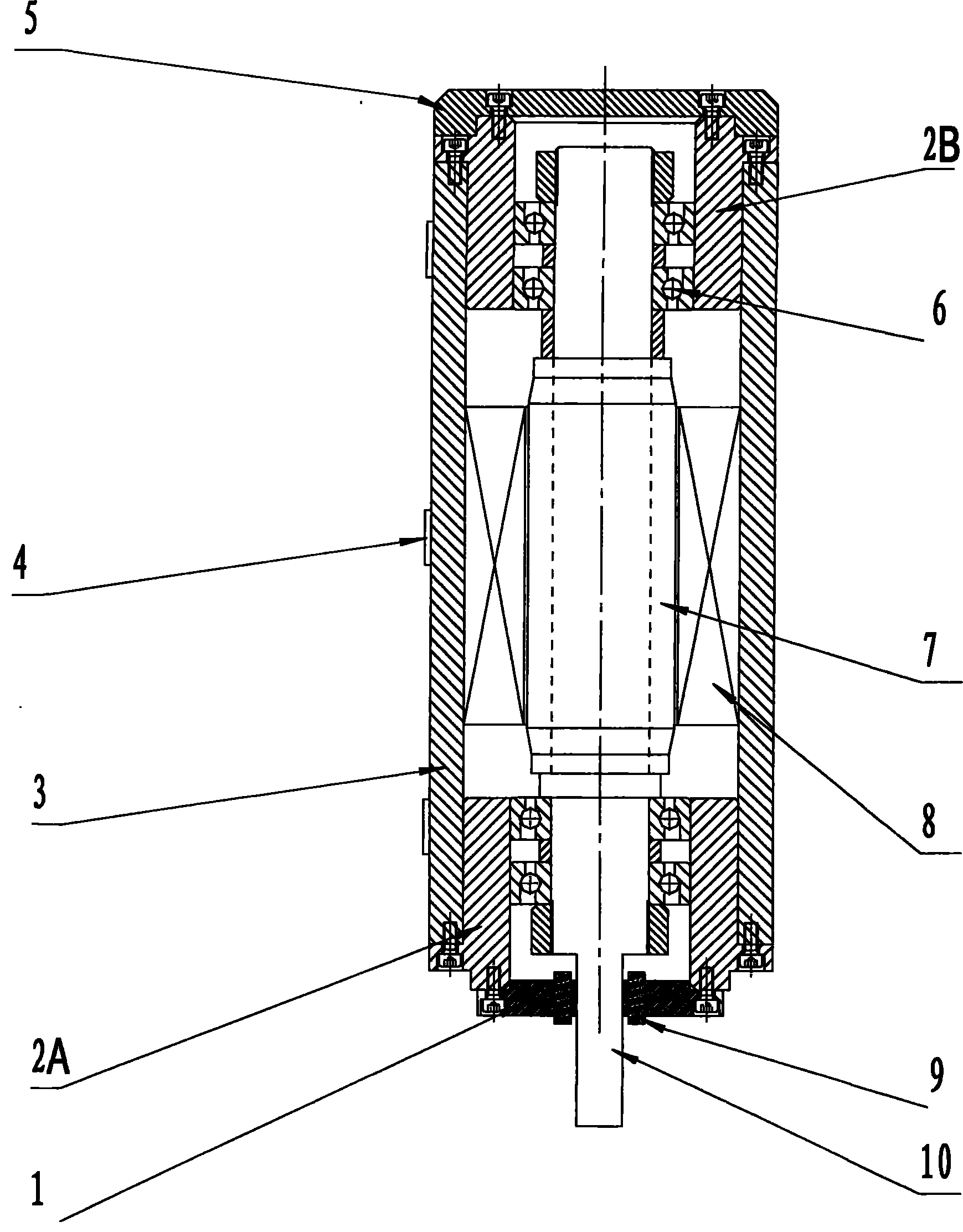
[0014] As shown in the drawings, a stator 8 is fixed on the inner cylindrical surface of the sleeve 3, and the main shaft 10 is installed in the bearing 6 of the main shaft front bearing seat 2A and the main shaft rear bearing seat 2B installed at both ends of the sleeve 3 hole, and is fixed on the main shaft 10. The upper mover 7 and the stator 8 are rotationally matched, and the non-contact displacement sensor 9 used to measure the thermal elongation of the mover 7 relative to the sleeve 3 is set on the front main shaft, and the non-contact displacement sensor 9 is fixed on the front bearing of the main shaft In the end cover 1, the temperature sensor 4 for measuring the temperature distribution of the sleeve 3 is arranged axially evenly on the outer cylindrical surface of the sleeve 3, the sleeve 3, the main shaft front bearing end cover 1 and the main shaft rear bear...


PUM


Abstract

The invention discloses an electric main shaft structure capable of realizing self-examination of thermal extension. A stator is fixed on an inner cylindrical surface of a sleeve, wherein a main shaft is arranged in a front main shaft bearing seat and a rear main shaft bearing at the two ends of a sleeve hole; a rotor fixed on the main shaft is in running fit with the stator; a non-contact displacement sensor for measuring the thermal extension of the rotor relative to the sleeve is sleeved on the main shaft at the front end; the non-contact displacement sensor is fixed in a front main shaft bearing end cover; and a temperature sensor for measuring temperature distribution of the sleeve is uniformly arranged on an outer cylindrical surface of the sleeve. By the self-examination of the thermal extension, the machining error caused by the thermal extension can be very easily compensated. The structure can detect the thermal extension of the main shaft in real time, also detect axial play of the main shaft and solve the problem of measuring the thermal extension of the main shaft in a machining field. The main shaft structure is particularly applied to aerospace and high-accuracy machining of precise moulds.

Description

technical field [0001] The invention relates to an electric spindle structure, in particular to an electric spindle structure with thermal extension self-detection. Background technique [0002] Electric spindle is the abbreviation of "high frequency spindle", which is a built-in motor spindle unit. It shortens the length of the main transmission chain of the machine tool to zero, realizes the "zero transmission" of the machine tool, and has the advantages of compact structure, high mechanical efficiency, high rotation speed and rotation accuracy, low noise, and small vibration. The application of the electric spindle has greatly improved the processing efficiency and quality, and reduced the product cost. It is one of the most important functional components of modern high-speed and high-precision machine tools. However, as the speed of the motorized spindle increases, the magnetic effect of the mover and stator generates heat, and the frictional heat generated by the bear...

Claims


Application Information

Patent Timeline
IPC IPC(8): H02K7/10H02K11/00H02K11/25
Inventor 贺永傅建中沈洪垚姚鑫骅甘文峰陈子辰
Owner ZHEJIANG UNIV
Why Eureka
Try Eureka