Heat abstractor

A heat dissipation device and heat dissipation fin technology, which is applied in the direction of heat dissipation fins, indirect heat exchangers, heat exchange equipment, etc., can solve problems such as easy overlapping, increased gaps, and reduced overall length of heat dissipation fin groups. The effect of reducing, not easily deformed, and reducing the defective rate

Inactive Publication Date: 2011-01-12
FURUI PRECISE COMPONENT (KUNSHAN) CO LTD +1
View PDF6 Cites 6 Cited by
  • Summary
  • Abstract
  • Description
  • Claims
  • Application Information

AI Technical Summary

Problems solved by technology

Due to the difference in height, the first heat dissipation fin set and the second heat dissipation fin set tend to overlap during assembly, resulting in a reduction in the overall length of the heat dissipation fin set and an increase in the gap between the heat dissipation fin set and other components of the notebook computer. Does not meet laptop safety regulations

Method used


Image

  • Heat abstractor
  • Heat abstractor
  • Heat abstractor

Examples


Embodiment Construction

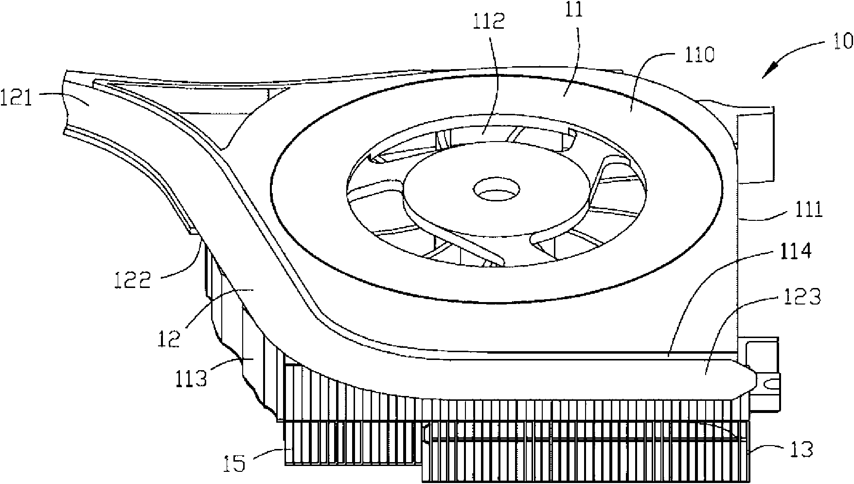
[0012] Such as figure 1 and figure 2 As shown, the heat dissipation device 10 includes a heat dissipation fan 11 , a heat pipe 12 , a first heat dissipation fin set 13 and a second heat dissipation fin set 15 . The top 110 and the bottom 111 of the cooling fan 11 are provided with an air inlet 112 , and the sidewall 113 of the cooling fan 11 is provided with an air outlet 114 . The heat pipe 12 is a flat heat pipe. The top surface 121 and the bottom surface 122 of the heat pipe 12 are flat. The first heat dissipation fin group 13 and the second heat dissipation fin group 15 are located at the air outlet 114 of the heat dissipation fan 11 and are arranged in a row and attached to the bottom of the condensation section 123 of the heat pipe 12. The second heat dissipation fin group 15 is located at the first heat dissipation On the left side of the fin set 13 , the height of the second heat dissipation fin set 15 is smaller than the height of the first heat dissipation fin set...


PUM


Abstract

The invention discloses a heat abstractor comprising a heat pipe, a first cooling fin group and a second cooling fin group, wherein the first cooling fin group is provided with a first cooling fin adjacent to the second cooling fin group; the second cooling fin group is provided with a second cooling fin adjacent to the first cooling fin group; the height of the first cooling fin group is different from the height of the second cooling fin group; and one of the bodies of the first cooling fin and the second cooling fin is provided with a boss which leans against the other body of the first cooling fin and the second cooling fin. Compared with the prior art, the heat abstractor of the invention is characterized in that the boss of the first cooling fin leans against the body of the second cooling fin to prevent the second cooling fin from being embedded into the first sag of the first cooling fin, thus, the overall length of the first cooling fin group and the second cooling fin group does not decrease, which conforms to the safety specification of a laptop and lowers the reject ratio of the finished product.

Description

technical field [0001] The invention relates to a heat dissipation device, in particular to a heat dissipation device for heat dissipation of electronic components. Background technique [0002] Existing heat dissipation devices generally include a heat absorbing plate, a heat pipe, and a heat dissipation fin group formed by stacking heat dissipation fins. Heat, and transfer the heat to the heat pipe, through the heat pipe to the cooling fin group, the heat is dissipated by the cooling fin group. [0003] Considering the internal structure design of the notebook computer, the heat dissipation fin group is often split into a first heat dissipation fin group and a second heat dissipation fin group which are adjacent and have different heights. Due to the difference in height, the first heat dissipation fin set and the second heat dissipation fin set tend to overlap during assembly, resulting in a reduction in the overall length of the heat dissipation fin set and an increase ...

Claims


Application Information

Patent Timeline
Patent Type & Authority Applications(China)
IPC IPC(8): H05K7/20H01L23/367H01L23/427G06F1/20
CPCH01L23/467H01L23/427G06F1/20H01L2924/0002F28D15/0275F28F2215/04H01L2924/00
Inventor 洪波张永张玮祥
Owner FURUI PRECISE COMPONENT (KUNSHAN) CO LTD
Why Eureka
Try Eureka