Reception device, transmission device, communication system, and communication method
A technology of receiving device and sending device, applied in the direction of transmission system, multiplex communication, digital transmission system, etc., can solve the problems of increased link capacity overhead, low throughput, increased end-to-end delay time, etc., to achieve The effect of reducing the number of retransmissions
- Summary
- Abstract
- Description
- Claims
- Application Information
AI Technical Summary
Problems solved by technology
Method used
Image

Examples
no. 1 Embodiment approach
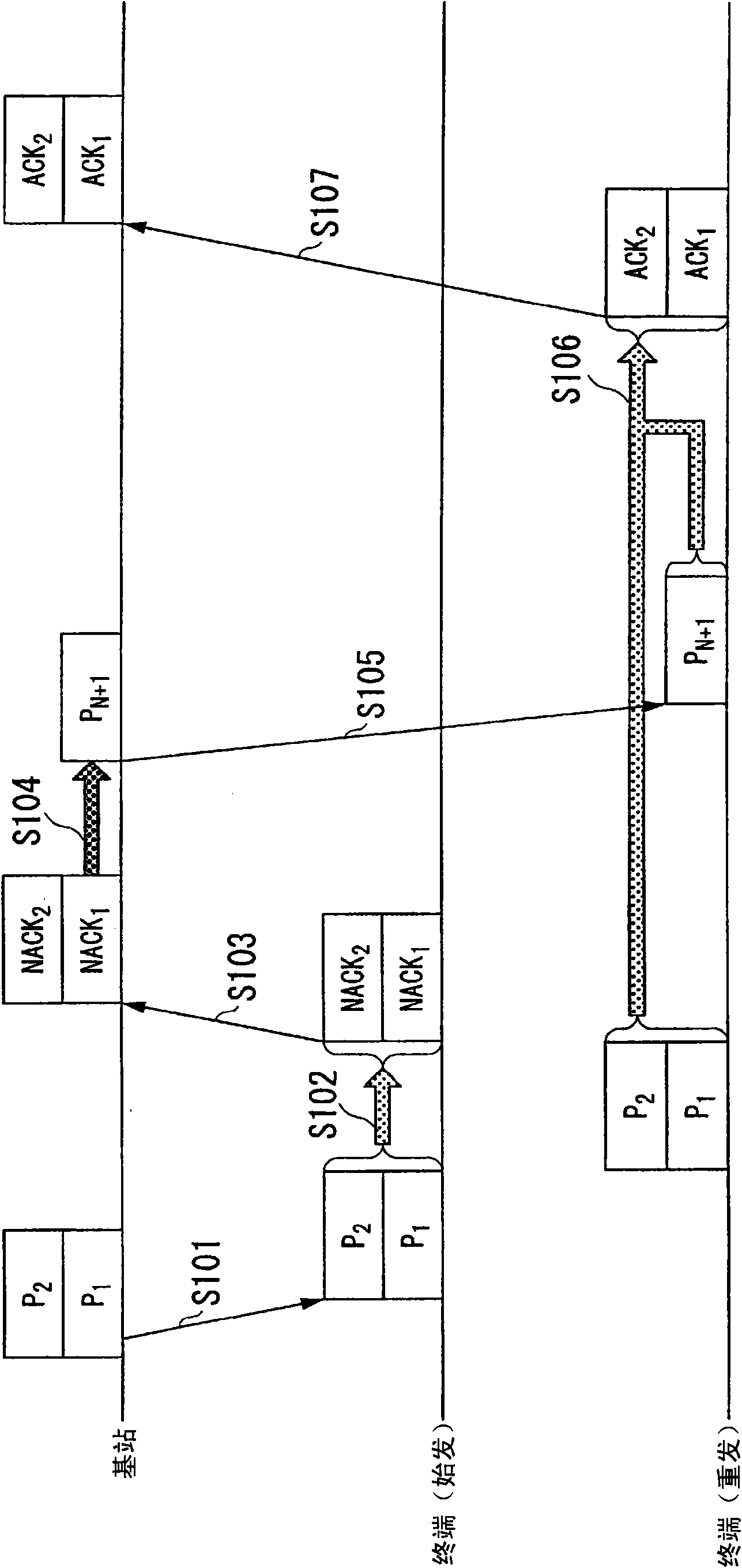
[0081] In the first embodiment, an iterative-parallel MCI canceller is used on the receiving device side. The iterative MCI canceller generates an MCI replica at the receiving side, and suppresses inter-code channel interference MCI by subtracting the MCI replica from the received signal.
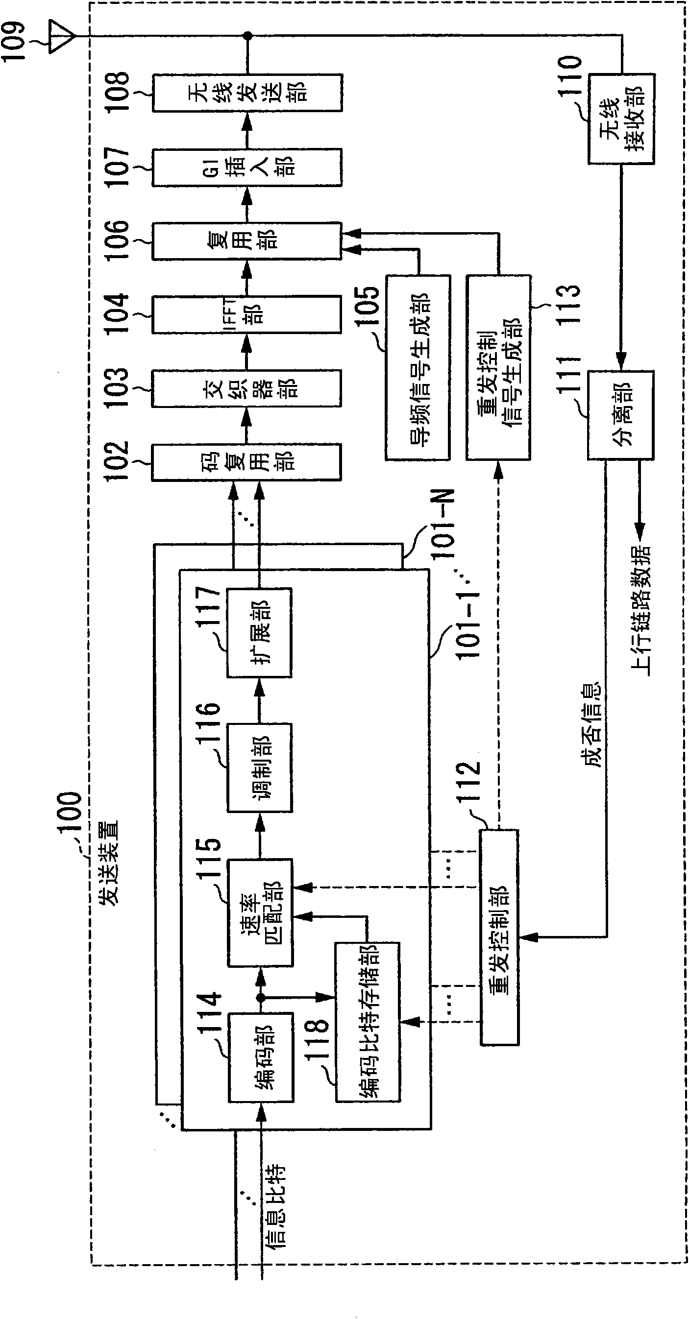
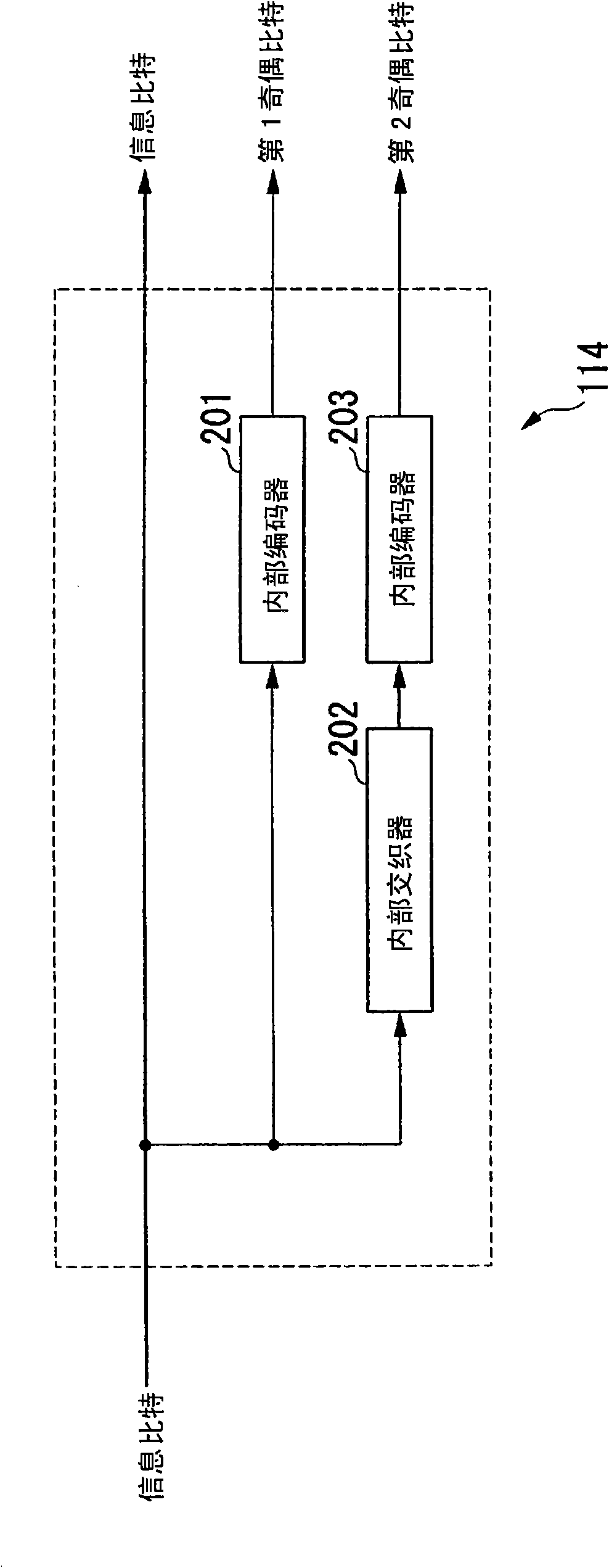
[0082] figure 2 It is a schematic block diagram showing the configuration of the transmission device 100 according to the first embodiment of the present invention. The transmission device 100 includes code channel signal generating units 101-1 to 101-N (where N is the number of code multiplexing), a code multiplexing unit 102, an interleaver unit 103, and an IFFT (Inverse Fast Fourier Transform: Inverse Fast Fourier Transform) part 104, pilot signal generation part 105, multiplexing part 106, GI (Guard Interval: guard interval) insertion part 107, wireless transmission part 108, antenna 109, wireless reception part 110, separation part 111, retransmission control part 112, Retransmissio...
no. 2 Embodiment approach
[0227] In the first embodiment, a case where an iterative parallel type MCI canceller is used on the receiving device 500 side has been described. In the second embodiment, a case where an iterative-sequential MCI canceller is used on the receiving device side will be described.
[0228] Figure 17 It is a schematic block diagram showing the configuration of the receiving device 1600 according to the second embodiment of the present invention. In addition, since the sending device can communicate with figure 2 The transmission device 100 shown is implemented with the same configuration, so description is omitted.
[0229] The reception device 1600 includes an antenna 1601, a radio reception unit 1602, a separation unit 1603, a channel estimation unit 1604, a channel estimation value storage unit 1605, a GI removal unit 1606, an FFT unit 1607, a received signal storage unit 1608, and a received packet management unit 1609. , an interference canceller unit 1610 , a bit LLR s...
no. 3 Embodiment approach
[0243] In the first and second embodiments, a case where packets are multiplexed with spreading codes and inter-code channel interference (MCI) is removed with a canceller has been described. In this embodiment, a case will be described in which packets are spatially multiplexed using MIMO (Multiple Input Multiple Output) and signals of other streams are removed by an interference canceller. In addition, a case where an iterative SIC (Successive Interference Canceller: successive interference canceller) is used as the interference canceller will be described.
[0244] Figure 19 It is a schematic block diagram showing the configuration of the transmission device 1800 according to the third embodiment of the present invention. Transmitter 1800 includes stream signal generation units 1801-1 to 1801-N (where N is the number of streams), antennas 1809-1 to 1809-N, wireless reception unit 1810, separation unit 1811, retransmission control unit 1812, retransmission Control signal ...
PUM
 Abstract
Description
Claims
Application Information
 - R&D
- Intellectual Property
- Life Sciences
- Materials
- Tech Scout
- Unparalleled Data Quality
- Higher Quality Content
- 60% Fewer Hallucinations
Browse by: Latest US Patents, China's latest patents, Technical Efficacy Thesaurus, Application Domain, Technology Topic, Popular Technical Reports.
© 2025 PatSnap. All rights reserved.Legal|Privacy policy|Modern Slavery Act Transparency Statement|Sitemap|About US| Contact US: help@patsnap.com