
Coarse fraction powder concentrator

A powder classifier and coarse-grained technology, applied in the direction of solid separation, separation of solids from solids with airflow, chemical instruments and methods, etc., can solve the problems of complex classification system, difficult lifting and sorting, grading, etc. Achieve the effect of high efficiency, long service life and uniform distribution

Inactive Publication Date: 2011-01-19
CHANGSHA UNIVERSITY
View PDF7 Cites 4 Cited by
  • Summary
  • Abstract
  • Description
  • Claims
  • Application Information

AI Technical Summary

Problems solved by technology

[0003] Theoretically speaking, general powder classifiers rely on wind force to overcome gravity to lift materials and classify and classify them. Since the wind-receiving area of ​​materials is proportional to the square of the particle size, and the weight is proportional to the cube of the particle size of the materials, it is large Granular materials and materials with large specific gravity are not easy to be lifted, sorted and classified
If the material separation particle size is large, as the particle size increases, the increase in gravity is much greater t

Method used


Image

  • Coarse fraction powder concentrator
  • Coarse fraction powder concentrator
  • Coarse fraction powder concentrator

Examples


Embodiment 1

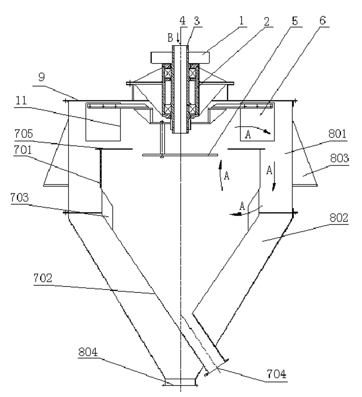
[0019] refer to figure 1 , this embodiment includes a machine base 803, a bearing seat 2, a transmission wheel 1, a hollow main shaft 3, a spreading disc 5, a large fan blade 6, an inner casing, and an outer casing, and the bearing seat 2 is installed on the machine cover 9; The hollow main shaft 3 is installed on the bearing seat 2 through a bearing, and the feeding port is arranged above the hollow main shaft; the transmission wheel 1, the spreading disc 5, and the large fan blade 6 are assembled on the hollow main shaft 3 to form a rotatable rotor part ,; the outer casing is composed of two parts: the upper outer casing 801 and the lower outer casing 802. The machine base 803 is arranged outside the outer casing for the installation of the machine, and the lower part of the lower outer casing 802 is provided with a fine powder outlet 804; the inner The casing is placed in the inner cavity formed by the outer casing. The inner casing is composed of an upper inner casing 701 ...

Embodiment 2

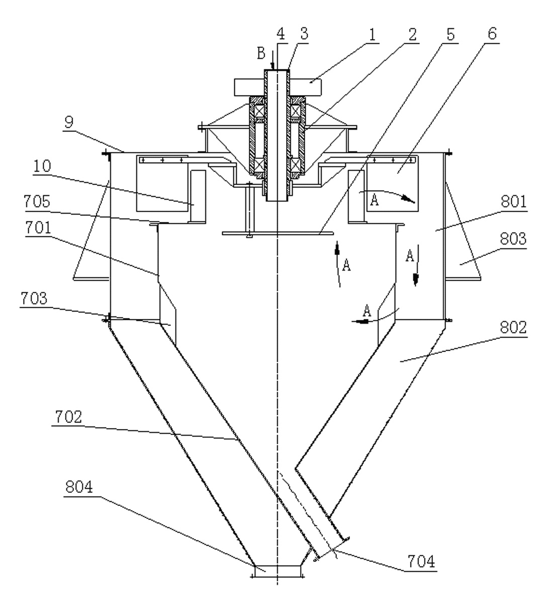
[0022] refer to figure 2 The difference between this embodiment and Embodiment 1 is only that a through-type annular powder separating blade 10 is added between the opening above the upper inner casing 701 and the cover 9 . The rest are the same as in Example 1. Only the fine materials that meet the particle size requirements can enter the fine powder area through the through-type annular powder separation blade 10 to realize the second classification, which is conducive to the realization of strict control of the particle size of the fine powder. The structure is simple and the classification efficiency is high.

Embodiment 3

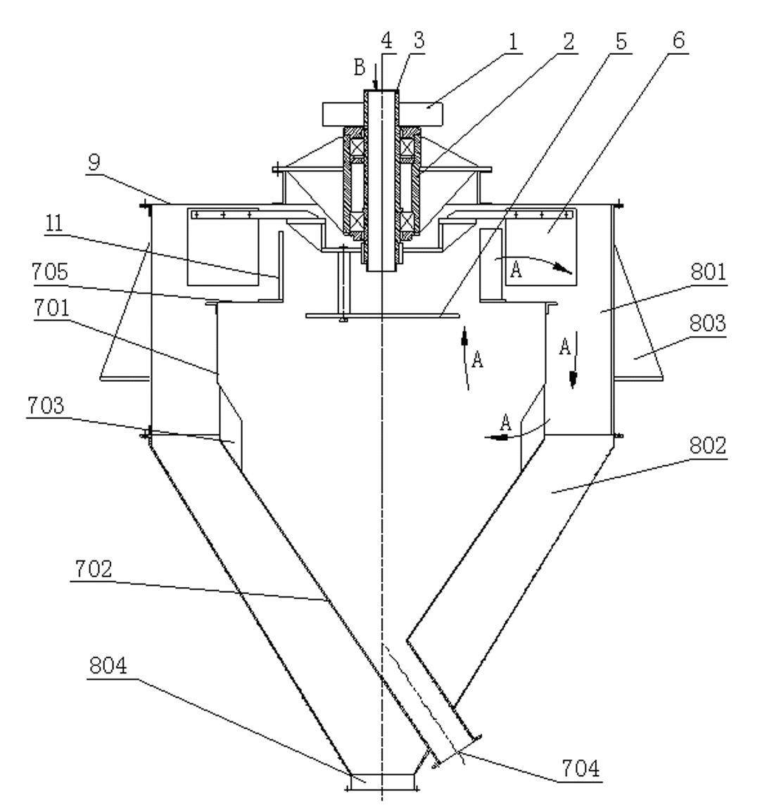
[0024] refer to image 3 , the difference between this embodiment and the first embodiment is only that a screen 11 is added between the upper inner casing 701 and the cover 9 . The rest are the same as in Example 1. Only the fine powder materials that pass through the sieve holes of the screen mesh 11 can enter the fine powder area, and the second classification is realized, which is conducive to the strict control of the particle size of the fine powder.

[0025] The sieve 11 is different from ordinary sieves for screening materials in two points: First, the materials entering the sieve have been classified by air flow, and the sieve only needs to block a small amount of coarser grades from entering the fine powder area, and does not need to be processed like ordinary sieves. All materials; Second, the materials entering the screen are suspended in the gas, the screening efficiency is high and the screen holes are not easily blocked, unlike ordinary screens that rely on gra...


PUM


Abstract

The invention relates to a coarse fraction powder concentrator which comprises an engine base, a bearing block, a transmission wheel, a hollow spindle, a spreading disk, a large fan blade, an inner shell and an outer shell, wherein the bearing block is arranged on an engine cover; the hollow spindle is arranged on the bearing block through a bearing, and a material inlet is arranged above the hollow spindle; the transmission wheel, the spreading disk and the large fan blade are assembled on the hollow spindle to form a rotor component capable of rotating; the outer shell consists of an upper outer shell and a lower outer shell; the engine base is arranged outside the outer shell; the lower part of the lower outer shell is provided with a fine powder outlet; the inner shell is arranged in an inner cavity formed by the outer shell and consists of an upper inner shell and a lower inner shell; the lower part of the lower inner shell is provided with a coarse powder outlet; and air return blades are arranged between the upper inner shell and the lower inner shell. The invention has the advantages of simple structure, high efficiency, large treatment capacity, long service life and no need of an external fan.

Description

technical field [0001] The invention relates to a dry separation device for powdery materials, in particular to a dry separation device for coarse-grained powdery materials used in industries such as non-metallic ores and new materials. Background technique [0002] The dry powder separators commonly used in the industry mainly include centrifugal, cyclone, and rotor types. , Coarse materials fall into the coarse powder area due to the action of gravity and centrifugal force, and the downward force is greater than the upward force, while the fine powder continues to enter the fine powder area. Since these powder separators adjust the fineness of the finished powder by changing the number of small fan blades and the speed of the classification impeller, the separation of coarse and fine powders must be performed with a larger classification height. [0003] Theoretically, powder separators generally rely on wind to overcome gravity to lift the materials and then sort and cla...

Claims


Application Information

Patent Timeline
IPC IPC(8): B07B7/083B07B7/01
Inventor 陈蕾
Owner CHANGSHA UNIVERSITY
Learn More