Forging die for manufacturing high-precision micro-vehicle crank shafts and manufacturing method thereof

A high-precision, crankshaft technology, used in the manufacture of tools, forging/pressing/hammer devices, forging/pressing/hammering machinery, etc., can solve the problems of shortening the service life of the mold, increasing the production cost, lack of guiding mechanism, etc. Service life, production cost saving, high filling and fullness effect

Inactive Publication Date: 2011-01-19
SOUTHWEST UNIVERSITY
View PDF4 Cites 14 Cited by
  • Summary
  • Abstract
  • Description
  • Claims
  • Application Information

AI Technical Summary

Problems solved by technology

In the prior art, due to the poor guiding precision of general forging equipment, and the lack of guiding mechanism between the upper and lower dies of the conventional mini-car crankshaft die itself, mold errors are prone to occur during the forging process, which in turn affects the accuracy of the product, such as: dimensions , shape accuracy, and product consistency cannot meet the high-precision requirements, and also greatly shorten the service life of the mold
In addition, with the lightweight requirements of high-precision crankshafts, the specifications of blanking materials are smaller and the number of auxiliary materials is less, which easily leads to insufficient filling, which in turn leads to unqualified products and low utilization of materials; this directly leads to increased production costs , the product profit is low, which is not conducive to the survival and development of related forging enterprises
[0003] In view of the above deficiencies, it is necessary to provide a new crankshaft mold to avoid the phenomenon of insufficient size and shape accuracy, poor consistency of finished products, incomplete product filling, high scrap rate, waste of materials and other phenomena caused by mold errors in the forging process. Extend tool life, resulting in cost savings and increased profit margins

Method used


Image

  • Forging die for manufacturing high-precision micro-vehicle crank shafts and manufacturing method thereof
  • Forging die for manufacturing high-precision micro-vehicle crank shafts and manufacturing method thereof
  • Forging die for manufacturing high-precision micro-vehicle crank shafts and manufacturing method thereof

Examples


Embodiment Construction

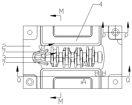
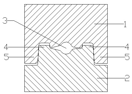
[0023] attached figure 1 It is the structural representation of the lower die of the present invention, with figure 2 to attach figure 1 Middle M-M sectional view (rotation) diagram, attached image 3 to attach figure 1 Middle A-A sectional view (rotation) diagram, attached Figure 4 to attach figure 1 Middle P-P sectional view, attached Figure 5 to attach figure 1 Middle Q-Q sectional view, attached Figure 6 to attach figure 1 Middle H-H sectional view, attached Figure 7 to attach figure 1 Middle C-C sectional view (rotation) diagram. As shown in the figure, the forging mold for manufacturing high-precision micro-car crankshaft of the present invention includes an upper mold 1, a lower mold 2 and a mold cavity 3 surrounded by the upper mold and the lower mold, and the lower mold 2 is located in the mold cavity 3 Guide grooves I are arranged axially on both sides, guide lugs I5 are arranged axially on both sides of the mold cavity on the upper mold 1 , and resis...


PUM

PropertyMeasurementUnit
radiusaaaaaaaaaa
heightaaaaaaaaaa
heightaaaaaaaaaa

Abstract

The invention provides a forging die for manufacturing high-precision micro-vehicle crank shafts. The forging die comprises an upper die, a lower die, a die cavity surrounded by the upper die and the lower die, wherein the lower die is axially provided with guide slots I positioned on the two sides of the die cavity; the upper die is correspondingly axially provided with guide ears I positioned on the two sides of die cavity; and the areas of the lower die corresponding to balancing plates on the two axial sides of a crank shaft are provided with resistance walls. The invention also provides a manufacturing method for the forging die, which comprises the following steps of: processing one die according to a benchmark pad and the size of a drawing; performing actual measurement and data acquisition on the processed die; and manufacturing a middle part and opposite angle guiding part of another die by using a method for ensuring clearance quantity through numerical control programming. The forging die for manufacturing the high-precision mini-car crank shafts has the advantages of higher precision of the product size and shape, better product consistency, greatly-prolonged service life, higher full degree of product filling, higher utilization ratio of materials and lower production cost.

Description

technical field [0001] The invention relates to a forging die for mechanical parts, in particular to a forging die for manufacturing a high-precision micro-car crankshaft and a manufacturing method thereof. Background technique [0002] The crankshaft is an important part of the engine to transmit power. It is subjected to shock loads and cyclic torques during work. The service condition is poor and the overall mechanical performance requirements are high. In recent years, manufacturers of micro-car crankshaft products are increasingly inclined to obtain forged steel crankshaft blanks with less or no machining, which requires lightweight and high-precision forged crankshaft blanks. In the prior art, due to the poor guiding precision of general forging equipment, and the lack of guiding mechanism between the upper and lower dies of the conventional mini-car crankshaft die itself, mold errors are prone to occur during the forging process, which in turn affects the accuracy of ...

Claims


Application Information

Patent Timeline
Patent Type & Authority Applications(China)
IPC IPC(8): B21J13/02B23K1/08
Inventor 李路
Owner SOUTHWEST UNIVERSITY
Why Eureka
Try Eureka