Ball valve

A technology for ball valves and valve stems, applied to valve details, valve devices, valve housing structures, etc., can solve the problems of small elastic force and shortened service life of valves, and achieve the effect of increasing elasticity and prolonging service life

Inactive Publication Date: 2011-01-19
XUANDA IND GRP
View PDF6 Cites 1 Cited by
  • Summary
  • Abstract
  • Description
  • Claims
  • Application Information

AI Technical Summary

Problems solved by technology

[0003] In order to solve the technical problems such as the small elastic force of the stuffing of the existing ball valve, which causes the service life of the valve to be shortened; Service life of the valve

Method used


Image

  • Ball valve
  • Ball valve
  • Ball valve

Examples


Embodiment Construction

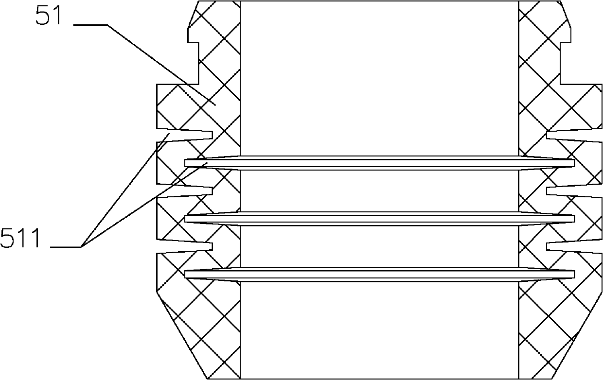
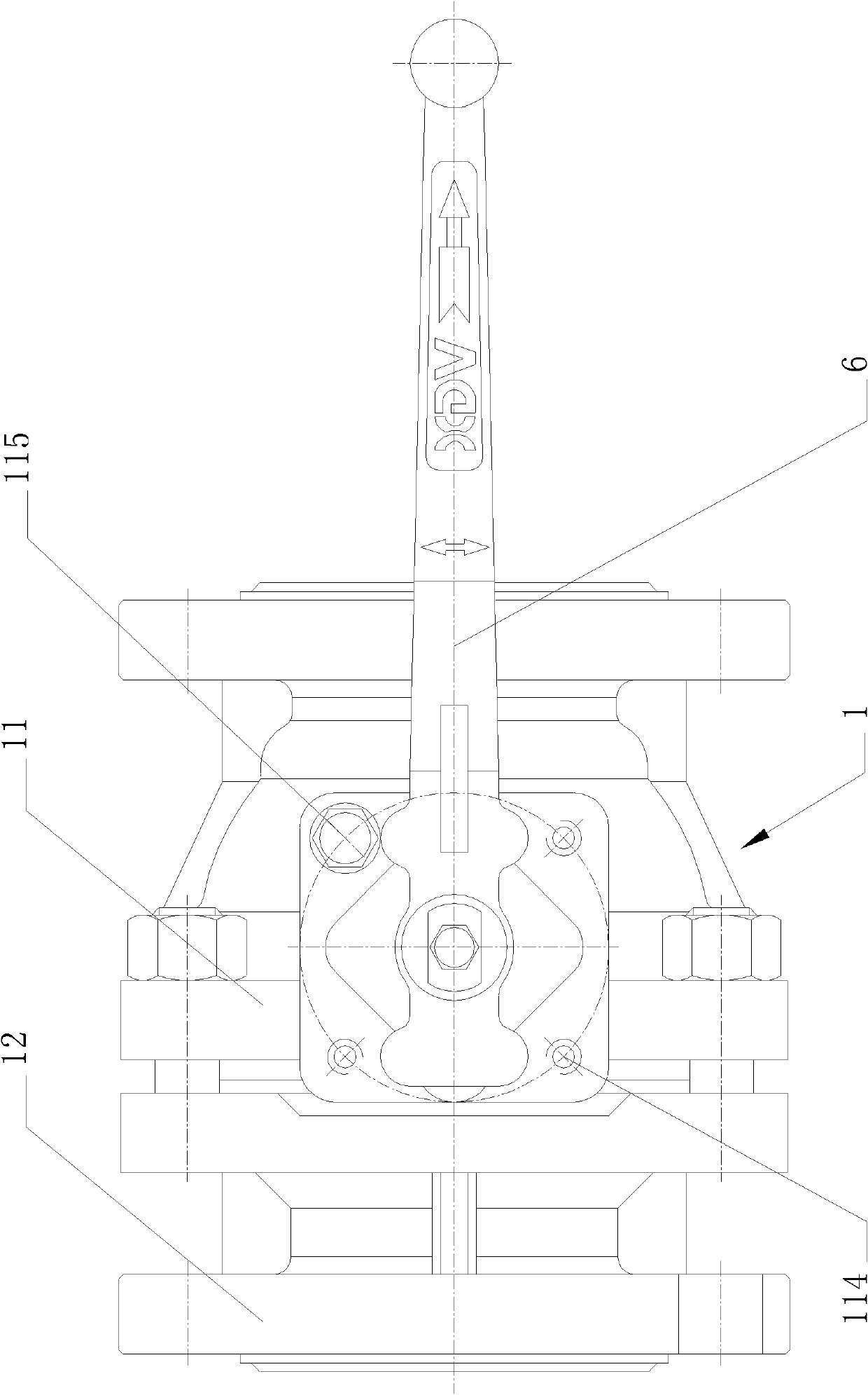
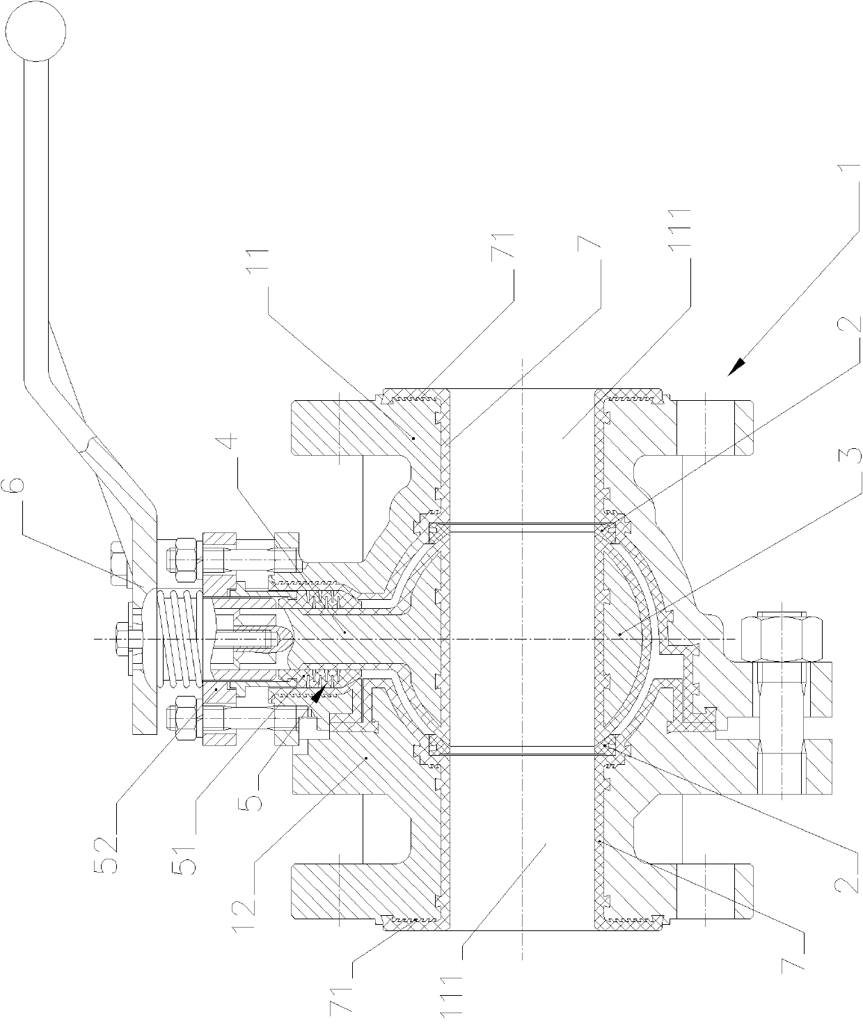
[0013] Embodiments of the present invention will be further described below in conjunction with accompanying drawings: Figure 1 to Figure 5 As shown, the present invention is a ball valve, which includes a valve body 1, a valve seat 2, a valve core 3, a valve stem 4, a packing mechanism 5 and an operating mechanism 6, and the valve seat 2 and the valve core 3 are placed Inside the valve body 1 and the valve core 3 closely fits with the valve seat 2, one end of the valve rod 4 is placed inside the valve body 1 and fixedly connected with the valve core 3, and the other end is placed outside the valve body 1 and connected with the operating mechanism 6, The packing mechanism 5 includes a packing 51 and a packing gland 52. The packing 51 is placed in the valve body 1 and sleeved outside the valve stem 4, and the inner and outer walls of the packing 51 are respectively connected to the valve body 1 and the valve body. The rod 4 is closely fitted, the packing gland 52 is sleeved ou...


PUM


Abstract

The invention relates to a ball valve, which mainly solves the technical problem that the valve is shortened in service life due to relatively small elastic force of padding of the traditional ball valve and other technical problems. The ball valve is characterized in that: multiple groups of mutually spaced annular open slots are reserved on the inner and outer side walls of the padding; and the bottom diameter of the annular open slot on the inner side wall is greater than that of the annular open slots on the outer side wall. The ball valve of the invention has the advantages that: the padding is designed as an integrated structure and the multiple groups of annular open slots are reserved on the inner and outer side walls of the padding, so that the elastic force of the padding is increased and the padding has sufficient pre-tightening force and adjustment space; and during use, if leakage occurs at a valve rod, the ball valve can conduct the function of sealing by adjusting a pressing cover of the padding to prop and press the padding, so that the service life of the valve is prolonged.

Description

technical field [0001] The invention relates to a valve, more specifically to a ball valve, which is mainly used in various pipeline systems. Background technique [0002] The ball valve is mainly used to cut off, distribute and change the flow direction of the medium in the pipeline. During use, it only needs to be rotated by 90° and a small rotational torque can be closed tightly. Existing ball valves include valve body, valve seat, valve core, valve stem, stuffing box, packing and packing gland, in order to prevent valve body, valve core and valve stem from being corroded by medium, The core and the valve stem are provided with a plastic lining layer; the packing is installed in the valve body through the stuffing box and sleeved outside the valve body, and its inner and outer walls are respectively attached to the plastic lining layer in the valve body and the plastic lining layer outside the ejector rod. The packing is mostly composed of multiple V-shaped washers, and ...

Claims


Application Information

Patent Timeline
Patent Type & Authority Applications(China)
IPC IPC(8): F16K5/06F16K5/08F16K27/06F16K41/02
Inventor 吕永和史庆泰叶际宣林忠孩
Owner XUANDA IND GRP
Why Eureka
Try Eureka