Optical coherence tomography system correction method

A correction method and data correction technology, applied in the field of OCT system correction, can solve problems such as the operation of the galvanometer drive signal and the nonlinear distortion of the OCT image.

Active Publication Date: 2012-05-30
SHENZHEN CERTAINN TECH CO LTD
View PDF0 Cites 0 Cited by
  • Summary
  • Abstract
  • Description
  • Claims
  • Application Information

AI Technical Summary

Problems solved by technology

like figure 1 As shown, at this time, the galvanometer cannot run completely according to the driving signal, that is, non-uniform high-speed vibration, resulting in nonlinear distortion in the longitudinal direction of the final OCT image.

Method used


Image

  • Optical coherence tomography system correction method
  • Optical coherence tomography system correction method
  • Optical coherence tomography system correction method

Examples


Embodiment Construction

[0018] The present invention will be further described below in conjunction with the accompanying drawings and preferred embodiments.

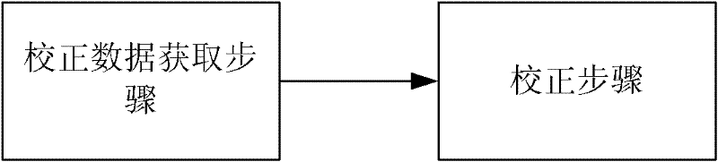
[0019] Such as figure 2 As shown, an OCT system calibration method includes the following steps: a calibration data acquisition step: the OCT system scans a reference slide to obtain the relationship function between the thickness value and the depth position at different positions; and, the calibration step: according to the The relationship function between the thickness value and the depth position is used to correct the acquired detection data.

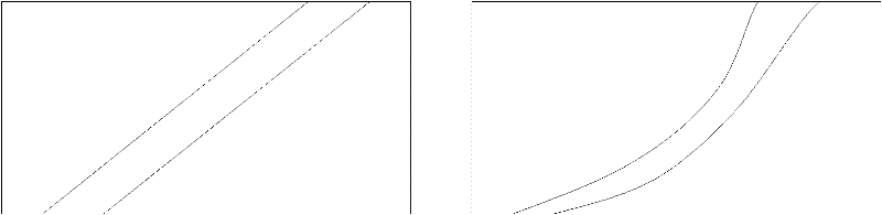
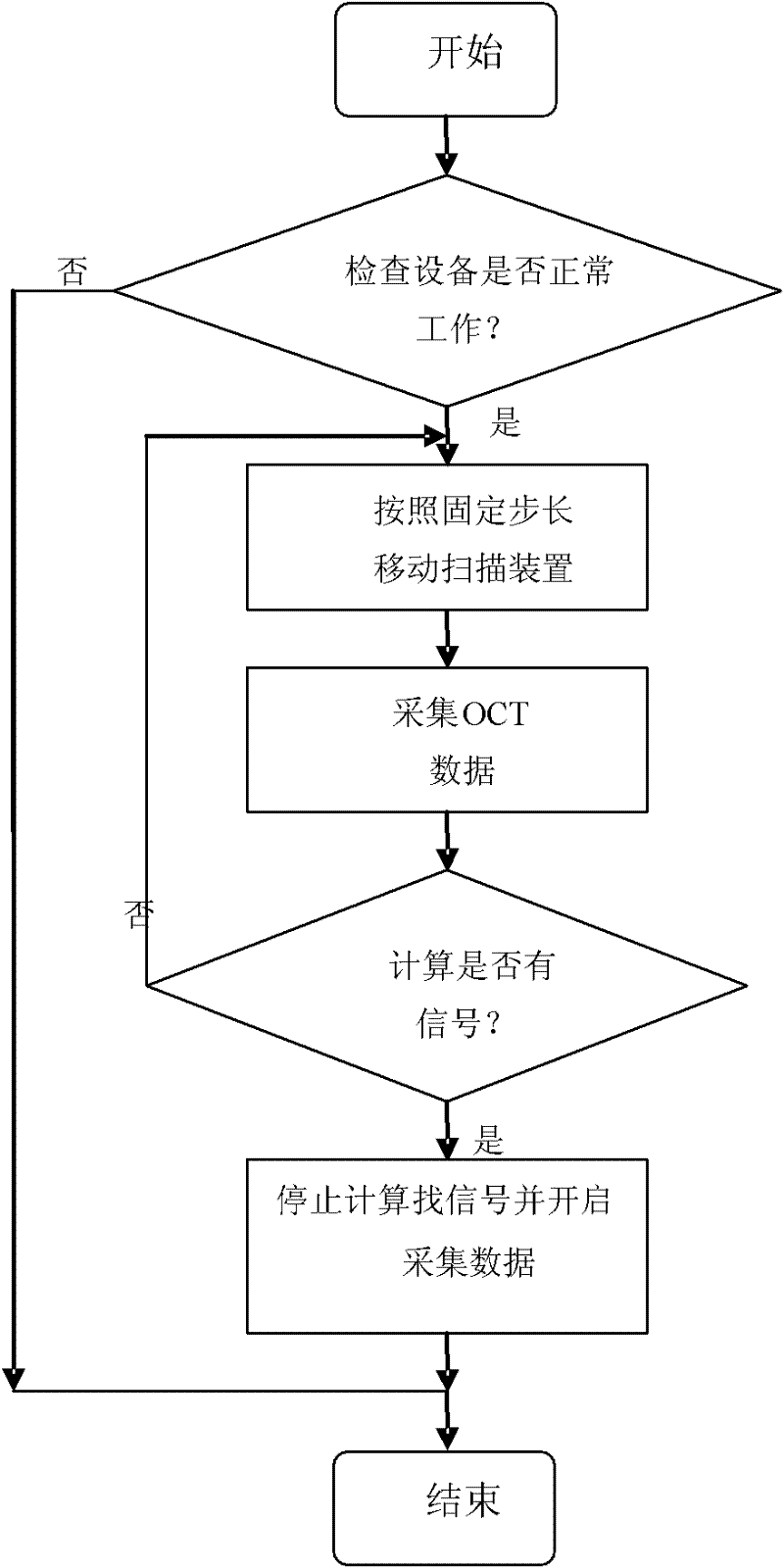
[0020] Wherein, the transparent reference glass slide with a thickness of ten microns is thicker than the resolution of the OCT system. The OCT system automatically searches for the signals on the upper and lower surfaces of the reference slide. When both layers of signals enter the picture, it starts to collect, and slowly moves the height of the sample to measure again. Repeatedly, a series of...


PUM


Abstract

The invention provides an optical coherence tomography (OCT) system correction method. The method comprises the steps of obtaining correction data and correcting, wherein in the step of obtaining correction data, the OCT system scans a reference slide to obtain the relation function between the reference slide measured value and different depth positions; and in the correcting step, the obtained detection data are corrected according to the relation function between the thickness and the depth positions.

Description

technical field [0001] The invention relates to an OCT system calibration method. Background technique [0002] The OCT (Optical Coherence Tomography) system uses the galvanometer in the fast scanning delay line (RSOD) to vibrate back and forth to change the optical path of the reference arm, thereby realizing the depth direction scanning of the OCT system. In theory, a signal is applied to the galvanometer to make it vibrate back and forth at a constant speed to achieve a uniform scan in the depth direction of the OCT system. However, in an actual system, since it is necessary to increase the scanning rate and imaging rate of the OCT system as much as possible, the galvanometer is usually oscillated at a high speed close to its limit. Such as figure 1 As shown, at this time, the galvanometer cannot run completely according to the driving signal, that is, non-uniform high-speed vibration, resulting in nonlinear distortion in the longitudinal direction of the final OCT imag...

Claims


Application Information

Patent Timeline
Patent Type & Authority Patents(China)
IPC IPC(8): G01B11/06G02B26/10
Inventor 陈常祥代祥松
Owner SHENZHEN CERTAINN TECH CO LTD
Why Eureka
Try Eureka