Ejector-type refrigeration cycle device

A refrigeration cycle and ejector technology, applied in the field of ejector refrigeration cycle devices, can solve the problems of high COP, inability to supply refrigerant, and unavoidable COP reduction, and achieve the effect of improving COP

Inactive Publication Date: 2011-01-19
DENSO CORP
View PDF6 Cites 29 Cited by
  • Summary
  • Abstract
  • Description
  • Claims
  • Application Information

AI Technical Summary

Problems solved by technology

However, the amount of pressurization in the diffuser portion of the injector is reduced according to the decrease in the flow rate of the driving flow, so that it cannot avoid the decrease in COP
In addition, the COP is also reduced because the refrigerant cannot be supplied to the suction side evaporator
[0028] That is, in an ejector type refrigeration cycle device using an ejector as a refrigerant decompression device, it may be difficult to operate the cycle stably while having a high COP if a change in the flow rate of the driving flow is caused.

Method used


Image

  • Ejector-type refrigeration cycle device
  • Ejector-type refrigeration cycle device
  • Ejector-type refrigeration cycle device

Examples


no. 1 example

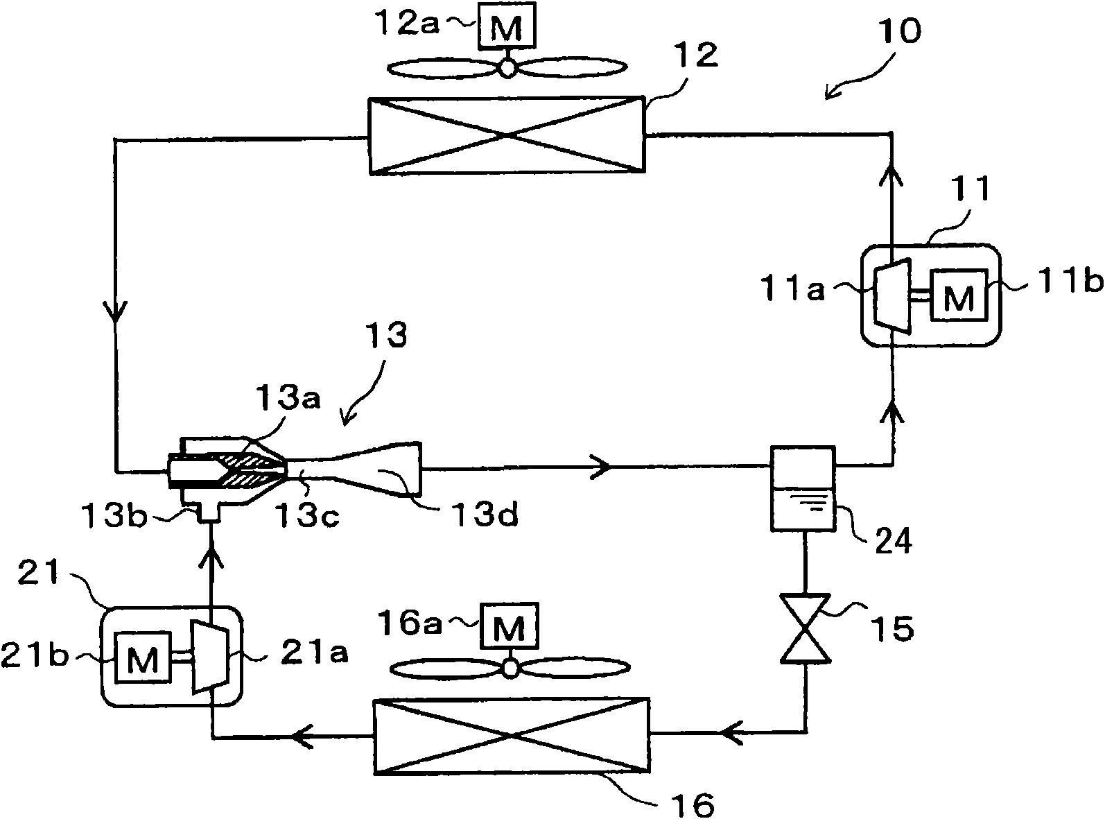
[0226] In this example, reference will be made to figure 1 and 2 The ejector type refrigeration cycle device of the present invention used in a refrigerator will be described. The refrigerator is used to cool a refrigerated inner chamber, which is a space to be cooled, to an extremely low temperature, for example, in a range between -30°C and -10°C. figure 1 It is the whole schematic diagram of the ejector type refrigeration cycle apparatus 10 of this embodiment.

[0227] In the ejector type refrigeration cycle device 10, the first compressor 11 is configured to suck refrigerant, compress the sucked refrigerant, and discharge the compressed refrigerant. For example, the first compressor 11 is an electric compressor in which a first compression mechanism 11a having a fixed displacement is driven by a first motor 11b. For example, various compression mechanisms such as a screw-type compression mechanism, a vane-type compression mechanism, and the like can be used as the fir...

no. 2 example

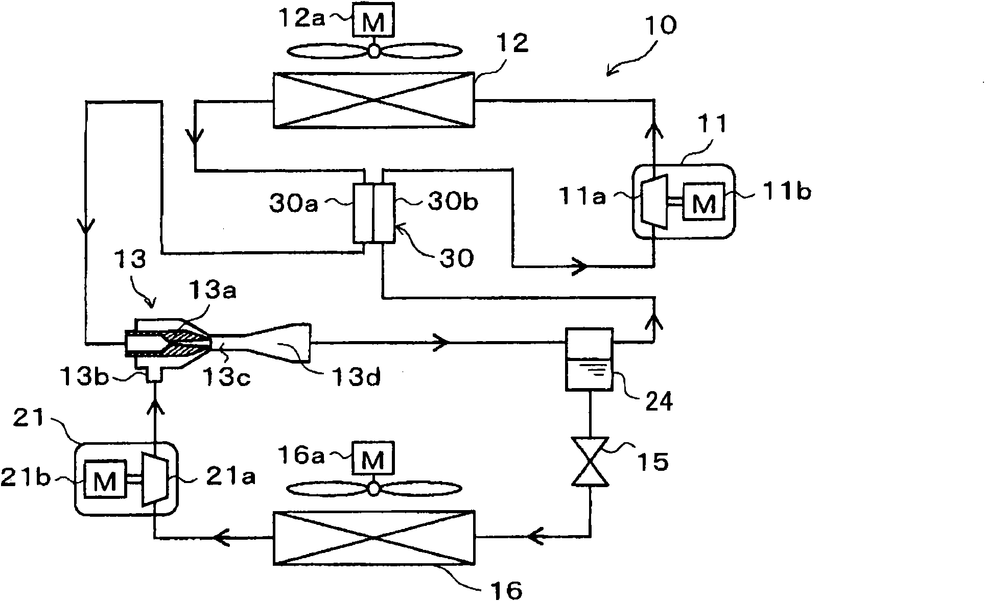
[0263] In this example, as in image 3 In the overall schematic diagram of , an internal heat exchanger 30 is added to the ejector refrigeration cycle device 10 of the first embodiment, in which, the refrigerant flowing out from the radiator 12 and the low-pressure side refrigerant in the cycle perform heat exchange . exist image 3 In , components similar to or corresponding to the first embodiment are denoted by the same reference numerals. This is also the same in the subsequent drawings.

[0264]The internal heat exchanger 30 is used between the refrigerant flowing through the high-pressure side refrigerant passage 30a from the refrigerant outlet side of the radiator 12 and the refrigerant flowing through the low-pressure side refrigerant passage 30b and sucked into the first compression mechanism 11a. heat exchange between them. Therefore, the low-pressure side refrigerant in the cycle of the present embodiment is the refrigerant to be sucked into the first compressio...

no. 3 example

[0272] In this example, as in Figure 5 In the overall schematic diagram of FIG. 2 , compared with the ejector refrigeration cycle device 10 of the first embodiment, an internal heat exchanger 31 is added. The basic structure of the internal heat exchanger 31 is similar to that of the internal heat exchanger 30 of the second embodiment.

[0273] The internal heat exchanger 31 is used between the refrigerant flowing through the high-pressure side refrigerant passage 31a from the refrigerant outlet side of the radiator 12 and the refrigerant flowing through the low-pressure side refrigerant passage 31b and sucked into the second compression mechanism 21a. heat exchange between them. Therefore, the low-pressure side refrigerant in the cycle of the present embodiment is the refrigerant to be sucked into the second compression mechanism 21a. Other configurations in this embodiment are similar to the first embodiment.

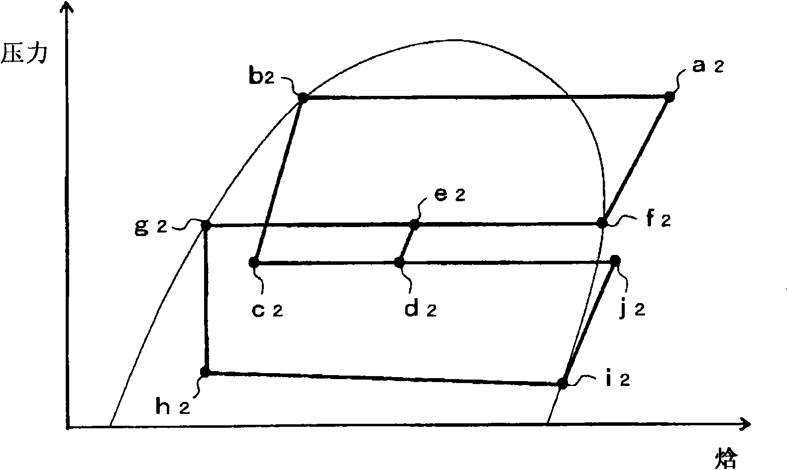
[0274] Next, refer to Image 6 The Mollier diagram describe...


PUM


Abstract

In an ejector-type refrigeration cycle device provided with a first compression mechanism (11a) and a second compression mechanism (21a), a refrigerant outlet of a suction-side evaporator (16) is connected to a refrigerant suction port (13b) of an ejector (13), and the second compression mechanism (21a) is provided between the suction-side evaporator (16) and the refrigerant suction port (13b) ofthe ejector (13). Thus, even under an operation condition such that the suction capability of the ejector (13) reduces with a reduction in the flow rate of the driving flow of the ejector (13), the suction capability of the ejector (13) can be assisted by the second compression mechanism (21a). Consequently, even when the flow rate of the driving flow changes, the ejector-type refrigeration cycledevice can be stably operated.

Description

[0001] Cross References to Related Applications [0002] This application is based on Japanese Patent Application No.2008-108676 filed on April 18, 2008, Japanese Patent Application No.2008-259501 filed on October 6, 2008, Japanese Patent Application No. 2008-259502, Japanese Patent Application No. 2008-259503 filed on October 6, 2008, Japanese Patent Application No. 2008-259504 filed on October 6, 2008, Japanese Patent Application No. 2008 filed on December 9, 2008 . 2008-312958, and Japanese Patent Application No. 2008-312959 filed on December 9, 2008, the entire contents of which are hereby incorporated by reference. technical field [0003] The present application relates to an ejector refrigeration cycle device having an ejector. Background technique [0004] Generally, an ejector-type refrigeration cycle device is known to have an ejector that functions as a refrigerant decompression device and a refrigerant cycle device. For example, Patent Documents 1-3 describe ej...

Claims


Application Information

Patent Timeline
Patent Type & Authority Applications(China)
IPC IPC(8): F25B1/00F25B1/10F25B13/00F25B43/00F25B47/02
CPCF25B40/00F25B2341/0012F25B41/00F25B1/10
Inventor 押谷洋藤原健一西岛春幸山田悦久池本彻长野阳平
Owner DENSO CORP
Why Eureka
Try Eureka