Peripheral transmission center automatic rake-lifting thickener

A technology of peripheral transmission and concentrator, which is applied in the direction of settling tanks, feeding/discharging devices of settling tanks, chemical instruments and methods, etc., which can solve problems such as inability to lift rakes, derailment of rollers, and reduced service life of rubber wheels. Achieve the effects of improving concentration efficiency, avoiding displacement, and high degree of automation

Inactive Publication Date: 2011-01-26
淮北矿山机器制造有限公司
View PDF6 Cites 12 Cited by
  • Summary
  • Abstract
  • Description
  • Claims
  • Application Information

AI Technical Summary

Problems solved by technology

However, the peripheral drive concentrator also has problems such as the inability to lift the rake as a whole to varying degrees, especially the auxiliary rake in the cone pit cannot lift the rake, resulting in the defect of the concentrator pressing the rake.
In recent years, there have also been developed concentrators that raise rakes in the peripheral drive center, such as "a kind of automatic rake lift concentrator in the upper feeding peripheral roller drive center" (Patent No. CN200820211484.4). When lowering, the transmission frame also rises and falls with the hydraulic cylinder or the screw elevator, and the peripheral transmission device, floating wheel group, etc. shrink to the center of the concentration pool with the lifting of the transmission frame, and squeeze out to the outside of the concentration pool with the decline of the transmission frame. This kind of concentrator is not suitable for peripheral roller drive and peripheral rack drive, otherwise it is easy to cause the rollers to derail and the rack to fall off the track; The rubber wheel moves laterally frequently due to the lifting and lowering of the rubber wheel, causing the rubber wheel to be degummed, which greatly reduces the service life of the rubber wheel

Method used


Image

  • Peripheral transmission center automatic rake-lifting thickener
  • Peripheral transmission center automatic rake-lifting thickener
  • Peripheral transmission center automatic rake-lifting thickener

Examples


Embodiment Construction

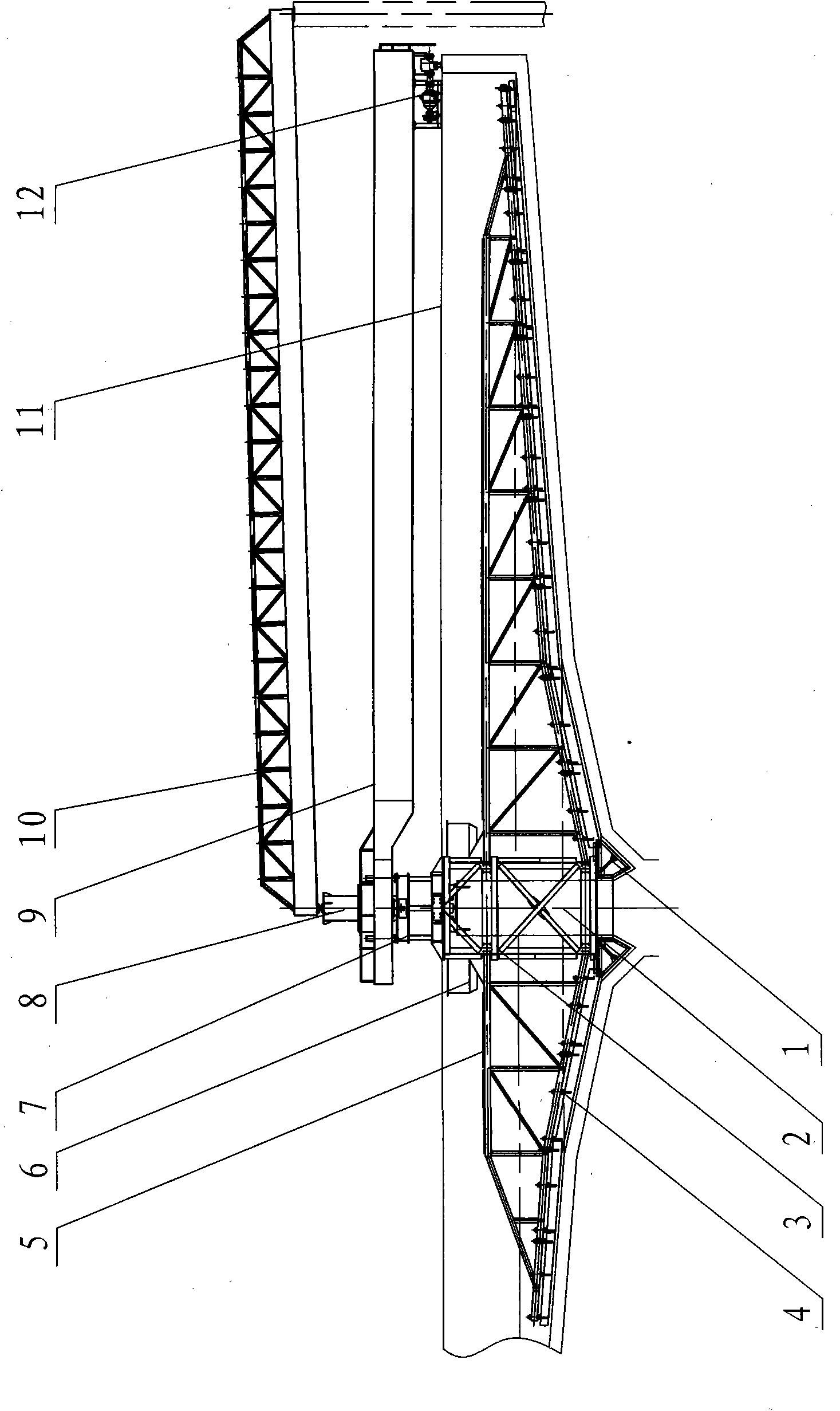
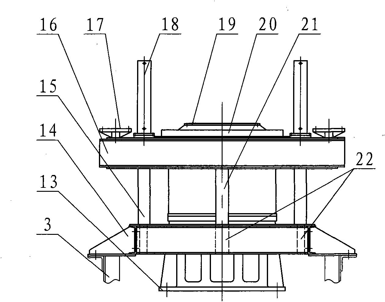
[0018] Such as figure 2 As shown, the central support 7 is composed of a fixed support 13, a seat ring 19, a slewing support 20, a rotating frame 16 and a sliding frame 14;

[0019] The fixed support 13 is columnar and plays the role of carrying the concentrator; the seat ring 19 is installed on the fixed support 13 and connected with the inner ring of the slewing support 20;

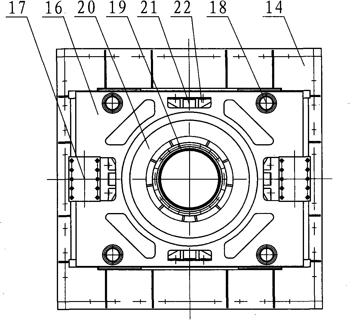
[0020] The slewing bearing 20 is a standard part, which is composed of an inner ring, a ball and an outer ring, and the inner ring and the outer ring can rotate freely;

[0021] The swivel frame 16 is connected with the outer ring of the slewing bearing 20, and four sliding keys 21 and four lifting cylinders 18 are evenly distributed on the periphery of the upper plane. Only the sliding key 21 is fixed on the side of the periphery of the rotating frame 16; the periphery of the sliding frame 14 is evenly distributed with four chutes 22, and the chute is connected up and down, and its position correspon...


PUM

PropertyMeasurementUnit
lengthaaaaaaaaaa

Abstract

The invention discloses a peripheral transmission center automatic rake-lifting thickener, which relates to the technical field of slurry thickeners and overcomes the defects that a conventional peripheral driven thickener cannot integrally lift a rake or a peripheral transmission device generates transverse displacement when a rake frame lifts so as to cause degluing of a tyre, derailing of a roller and the like. The thickener is characterized in that: a center bearing of the thickener consists of a fixed support, a seat ring, a slewing bearing, a rotary rack and a sliding rack; the rotary rack is provided with two hinged supports and four rake-lifting oil cylinders, and four sides of the rotary rack are provided with four sliding keys; four sides of the sliding rack are provided with four sliding grooves, the four sliding keys are inserted into the four sliding grooves respectively, and piston posts of the four rake-lifting oil cylinders are fixed on the sliding rack; the lower partof the sliding rack is fixedly connected with a rotary cage, and the lifting of the sliding rack can be controlled by driving the rake-lifting oil cylinders so that a rake rack is integrally lifted; and a transmission rack is not lifted along with the rake rack so that the transverse displacement of the transmission device is avoided and the transmission mode of the thickener is suitable for peripheral tyre transmission and peripheral roller transmission or peripheral rack transmission.

Description

technical field [0001] The invention relates to the field of slurry thickeners, in particular to a peripheral drive center automatic rake thickener. Background technique [0002] my country's current high-efficiency concentrators can be basically divided into two categories: central drive and peripheral drive. The central drive type concentrator has the advantages of large processing capacity and the ability to lift the rake as a whole, but its load-bearing bridge is too heavy, and the center driving arm is short, the transmission mechanism is stressed, it is easy to damage and fail, and its reliability is poor, so the diameter of the concentration pool is limited. . The peripheral transmission type concentrator, because the driving mechanism is arranged around the concentration pool, lengthens the driving force arm, which can reduce the force on the transmission mechanism, increase the reliability of the transmission mechanism and reduce the quality of the transmission mec...

Claims


Application Information

Patent Timeline
Patent Type & Authority Applications(China)
IPC IPC(8): B01D21/02B01D21/06B01D21/20B01D21/24
Inventor 胡善宏陈庆来马建新王春乔李从军
Owner 淮北矿山机器制造有限公司
Why Eureka
Try Eureka