Pulse blowback air purification equipment and dust cleaning method

An air purification equipment, pulse backflushing technology, applied in chemical instruments and methods, separation methods, dispersed particle separation and other directions, can solve the problem of inability to complete the cleaning of the filter cartridge, etc., and achieve novel structure design, good cleaning effect, and noise. small effect

Inactive Publication Date: 2011-01-26
NANFANG ENVIRONMENT PURIFYING EQUIP HANGZHOU
View PDF8 Cites 15 Cited by
  • Summary
  • Abstract
  • Description
  • Claims
  • Application Information

AI Technical Summary

Problems solved by technology

However, the cleaning of the inner wall o

Method used


Image

  • Pulse blowback air purification equipment and dust cleaning method
  • Pulse blowback air purification equipment and dust cleaning method
  • Pulse blowback air purification equipment and dust cleaning method

Examples


Embodiment 1

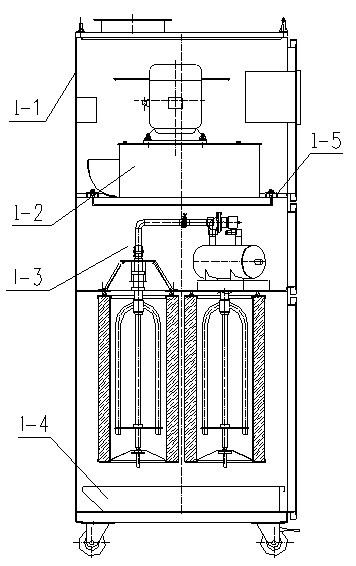
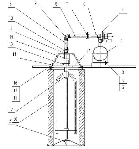
[0012] Embodiment 1: with reference to attached Figure 1-3 . Pulse blowback air purification equipment, which includes a chassis 1-1, fan assembly 1-2 and ash collection drawer 1-4, the fan assembly 1-2 is fixed in the chassis 1-1 through the fan pressure plate 1-5, and the pulse rotates to clean the dust The component 1-3 is located under the fan pressure plate 1-5 and is connected with the chassis type 1-1. The triangular positioning frame 14 in the pulse rotation cleaning component is fixed on the hole of the orifice plate through bolts 13, nuts 14 and gaskets 15. Around, the off-line dust cleaning cover 15 covers the hole of the orifice plate and is located in the triangular positioning frame 14, the upper end of the gas sleeve 12 is connected with the upper end plate of the triangular positioning frame 14, and the piston 13 is located in the gas sleeve 12 and under the action of the gas under pressure Moving up and down along the inner wall of the air sleeve, the upper ...

Embodiment 2

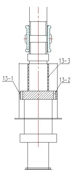
[0016] Embodiment 2: On the basis of embodiment 1, the self-cleaning method of pulse blowback air purification equipment, it comprises air purification equipment, when it comprises the filter cartridge 20 inner wall in the air purification dedusting equipment needs to regenerate, band compressed air The source supplies air to the air bag 2, opens the pulse solenoid valve 1, and the pulsed air flow with pressure enters the piston 13 through the air guide pipe 6 and 8, and then enters the spraying rotary frame 19 through the piston all the way, and passes through the piston rod on the upper part of the piston plug ring all the way. The air hole 13-3 enters the air cavity formed by the upper part of the piston plug ring 13-1 and the air sleeve 12 and forces the piston 13 to move up and down according to the pulse air flow. The swivel frame 19 rotates under the action of the airflow while cleaning the dust, so as to achieve the purpose of regeneration of the filter cartridge.


PUM


Abstract

The invention relates to a specific pulse blowback dust cleaning device with a blowing self-cleaning function and an air dust cleaning and purifying function for air purification equipment and a dust cleaning method. The specific pulse blowback dust cleaning device for the air purification equipment comprises a machine cabinet, a fan component and a dust collection drawer, wherein the fan component is fixed in the machine cabinet through a fan pressure plate; a pulse rotation dust cleaning component is positioned below the fan pressure plate and connected with the machine cabinet; a triangular positioning rack is fixed on the four sides of a hole of a hole plate; an offline dust cleaning cover is covered on the hole of the hole plate and positioned in the triangular positioning rack; the upper end of an air sleeve is connected with an upper end plate of the triangular positioning rack; a piston is positioned in the air sleeve and moves vertically along the inner wall of the air sleeve under the action of compressed air, and the upper end of a piston rod passes through the air sleeve and is in limited sliding fit with a limit nut; the limit unit is communicated with an air bag through an air duct and a pulse electromagnetic valve; the air bag is positioned on the plate of the hole plate; and the lower end of the piston rod is communicated with a blowing rotating rack which is positioned in a filter barrel, and the lower end of the blowing rotating rack is in rotary fit with a jacking hand wheel.

Description

technical field [0001] The invention relates to a pulse back-blowing air purification device and a dust removal method which not only have the function of spraying self-cleaning dust, but also have the function of air dust removal and purification, and belong to the field of air purification and dust removal equipment manufacturing. Background technique [0002] The patent number of the applicant is 200310116278.7, the name is "special vibrating dust removal mechanism for filter cartridge type dust removal and purification equipment", a special vibrating dust removal mechanism for filter cartridge type dust removal and purification equipment, which consists of positioning feet, connecting rods, eccentric mechanisms, vibrating The eccentric mechanism is driven by the motor. One end of the connecting rod is pinned to the transmission plate in the eccentric mechanism, and the other end is pinned to the positioning foot. The straight plate in the vibrating pressing frame and the ...

Claims


Application Information

Patent Timeline
IPC IPC(8): B01D46/24B01D46/42
Inventor 梅忠祥
Owner NANFANG ENVIRONMENT PURIFYING EQUIP HANGZHOU
Why Eureka
Try Eureka