

Bending die of double metal bracket stamping part
A technology for bending dies and stamping parts, which is applied in the field of stamping dies for stamping parts, can solve the problems of long time and prolonging the production preparation time of new stamping parts, and achieve the effect of good surface quality, smooth and beautiful appearance, and good interchangeability
Inactive Publication Date: 2011-01-26
ANHUI HUIJING MOLD R & D TECH
View PDF5 Cites 4 Cited by
- Summary
- Abstract
- Description
- Claims
- Application Information
AI Technical Summary
Problems solved by technology
Die design and manufacture require more time, which prolongs the production lead time of new stamping parts
Method used
View moreImage
Smart ImageViewing Examples


Examples
Embodiment Construction
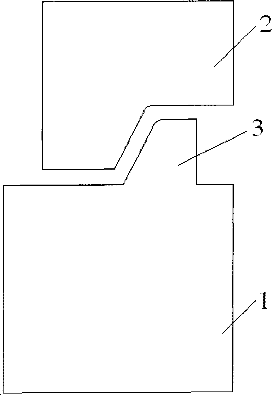
[0015] see figure 1 , a bending die for a stamping part of a bimetallic bracket, comprising a lower template 1, one side of the upper surface of the lower template 1 is provided with a boss 3, the inner surface of the boss 3 is a slope surface, and the top of the lower template 1 is provided with Punch 2, one side of the lower surface of the punch 2 is provided with a slope surface matching the boss 3 of the lower template 1 .
Login to View More PUM
 Abstract
The invention discloses a bending die of a double metal bracket stamping part, which comprises a lower mold plate and is characterized in that: a boss is formed on one side of the upper surface of the lower mold plate; the inner side of the boss is a slope surface; a punch head is arranged above the lower mold plate; and one side of the lower surface of the punch head is provided with a slope surface which is matched with the boss of the lower mold plate. The bending die of the double metal bracket stamping part has the advantages that: the structure is simple, and the bend stamping part has light weight, high rigidity, high strength, relatively high surface quality and a smooth and attractive appearance; and dimension precision is relatively high, and the identical modules have a uniform and homogeneous dimension and relatively high exchangeability, and the general assembling and can meet the general assembling and using requirements without further machining.
Description
technical field [0001] The invention relates to the field of stamping dies for stamping parts, in particular to a bending die for stamping parts of bimetallic brackets. Background technique [0002] Applying external force to plates, strips, pipes, profiles, etc. through punching machines and molds to cause plastic deformation or separation, so as to obtain workpieces of required shape and size. The workpieces obtained are stamping parts. [0003] Stamping parts are formed by applying external force to plates, strips, pipes and profiles by presses and molds to cause plastic deformation or separation to obtain workpieces (stamping parts) of required shape and size. Stamping and forging belong to plastic processing (or pressure processing) and are collectively called forging. The blanks for stamping are mainly hot-rolled and cold-rolled steel sheets and strips. [0004] Compared with castings and forgings, stamping parts have the characteristics of thinness, uniformity, ligh...
Claims
Login to View More Application Information
Patent Timeline
 Patent Type & AuthorityApplications(China)
IPC IPC(8): B21D37/10B21D7/02
Inventor于海利
OwnerANHUI HUIJING MOLD R & D TECH