
Earth residue conveyor K-P vibratory feeder in cement production technique

A cement production process, vibrating feeder technology, applied in conveyors, vibrating conveyors, transportation and packaging, etc., can solve the problems of material transport not going away, long accumulated maintenance time, etc., to protect the environment, improve service life, The effect of reducing manufacturing and operating costs

Inactive Publication Date: 2011-01-26
ANHUI CONCH KAWASAKI EQUIP MFG
View PDF6 Cites 3 Cited by
  • Summary
  • Abstract
  • Description
  • Claims
  • Application Information

AI Technical Summary

Problems solved by technology

Therefore, frequent repair welding is required, the cumulative maintenance time is long, and even the phenomenon that materials cannot be transported away occurs.

Method used


Image

  • Earth residue conveyor K-P vibratory feeder in cement production technique
  • Earth residue conveyor K-P vibratory feeder in cement production technique
  • Earth residue conveyor K-P vibratory feeder in cement production technique

Examples


Embodiment Construction

[0023] In the following, with reference to the accompanying drawings, through the description of the embodiments, the specific implementation of the present invention, such as the shape and structure of each component involved, the mutual position and connection relationship between each part, the function and working principle of each part, and the manufacturing process and operation and use methods, etc., are described in further detail to help those skilled in the art to have a more complete, accurate and in-depth understanding of the inventive concept and technical solutions of the present invention.

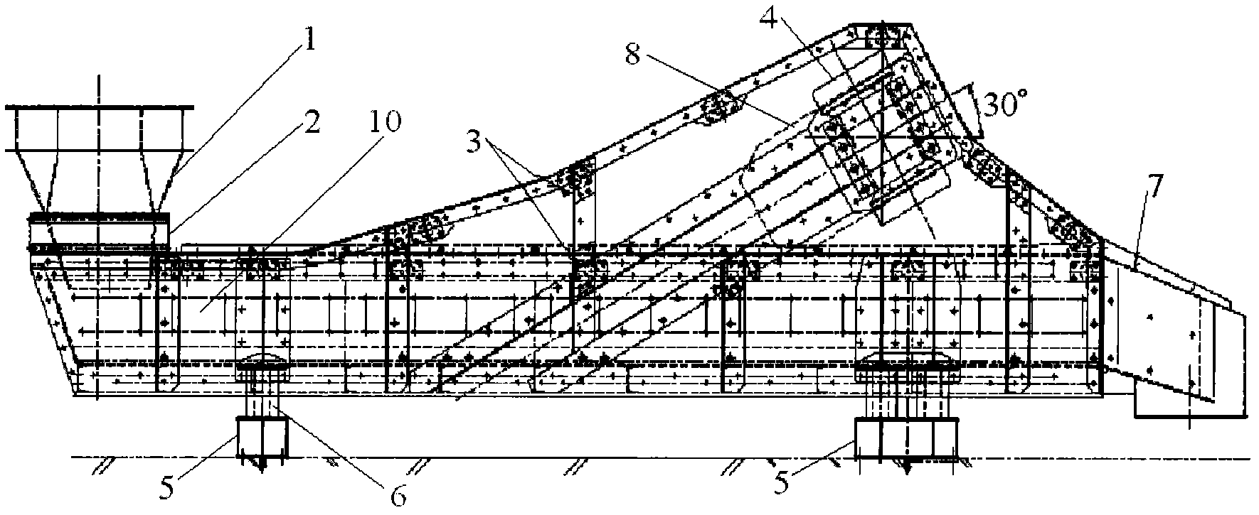
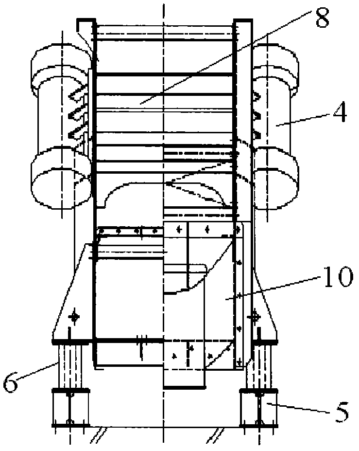
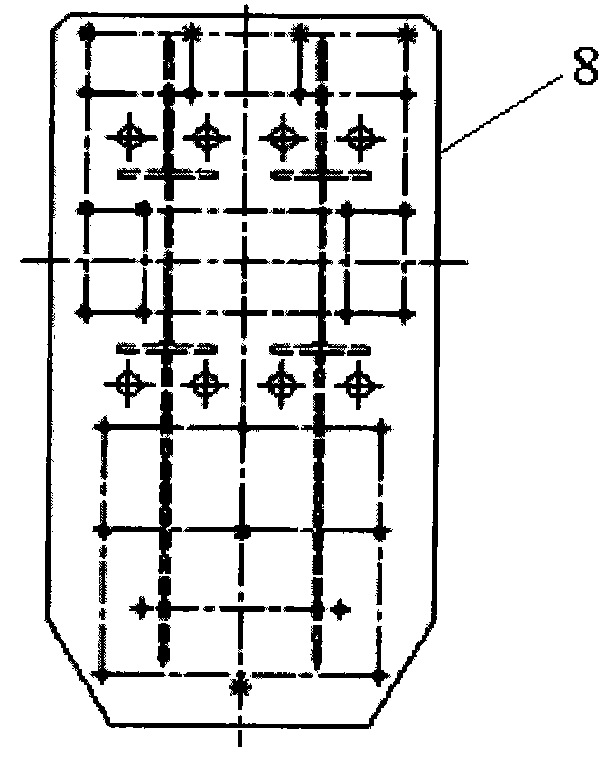
[0024] like Figure 1 to Figure 5 The expressed structure of the present invention is a K-P vibrating feeder of a soil slag conveying device in a cement production process, comprising a body conveying trough 10 set in a horizontal direction, a vibration motor 4, a vibration motor base 8, and a feeding chute 1 2. The discharging slide 7, the vibration motor 4 is fixedly conne...


PUM


Abstract

The invention discloses an earth residue conveyor K-P vibratory feeder in a cement production technique, which comprises a feeder body conveying chute (10), vibration motors (4), a vibration motor base (8), a feed trough (1) and a discharge trough (7), wherein the feeder body conveying chute (10) is arranged horizontally; the vibration motors (4) are fixed on the vibration motor base (8); by the way that the symmetrical plane of the two vibration motors (4) is the longitudinal vertical central plane of the feeder body conveying chute (10), the two vibration motors (4) are installed on two side faces of the vibration motor base (8); and the axial line of each vibration motor (4) is slanted relative to the feeder body conveying chute (10). By using the technical scheme, the invention can prolong the service life of the vibratory feeder and perform the function of environment protection. The vibratory feeder has the advantages of reasonable structure and convenient processing, and can effectively lower the manufacturing and operating cost.

Description

technical field [0001] The invention belongs to the technical field of construction material production process equipment, and relates to process equipment for cement production lines. More specifically, the invention relates to a K-P vibrating feeder, a soil slag conveying device in a cement production process. Background technique [0002] In order to meet the needs of CK-450 vertical mill feeding, currently cement production enterprises generally use the vibrating feeder matched with ATOX50 raw material mill. Under the action of alternating stress, cracks appeared in the shell weld of the vibrating feeder, especially near the vibrating motor. Therefore, frequent repair welding is required, and the accumulated maintenance time is long, and even the phenomenon that the material cannot be transported occurs. SUMMARY OF THE INVENTION [0003] The problem to be solved by the present invention is to provide a soil slag conveying device K-P vibrating feeder in the cement prod...

Claims


Application Information

Patent Timeline
IPC IPC(8): B65G27/04B65G27/10B65G27/08
Inventor 潘胡江王雷吴前松
Owner ANHUI CONCH KAWASAKI EQUIP MFG
Learn More