Method for debugging blade server by using BMC module
A blade server and module debugging technology, applied in the computer field, can solve the problems of expensive, inconvenient for hardware developers, and can only be debugged locally, and achieves the effect of powerful functions, convenient debugging without distance and flexible implementation
- Summary
- Abstract
- Description
- Claims
- Application Information
AI Technical Summary
Problems solved by technology
Method used
Image
Examples
Embodiment 1
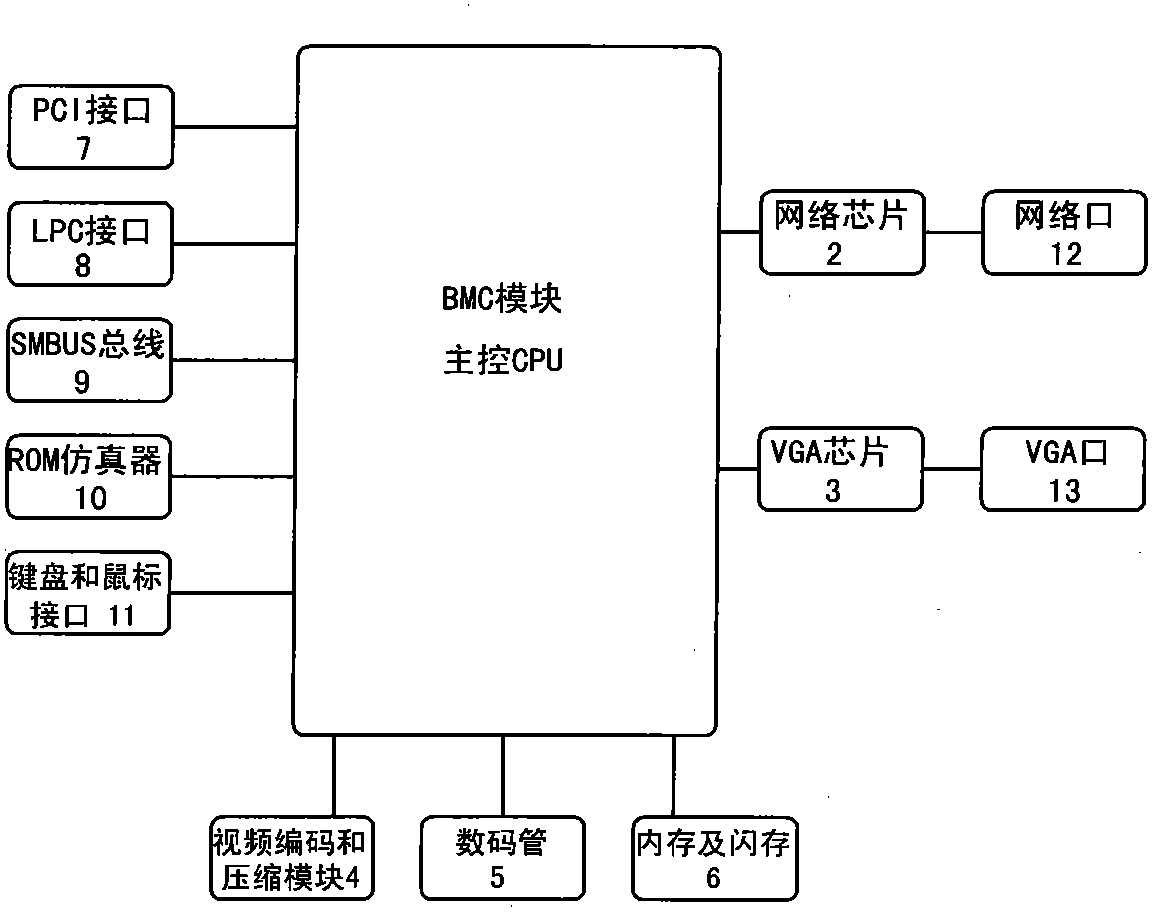
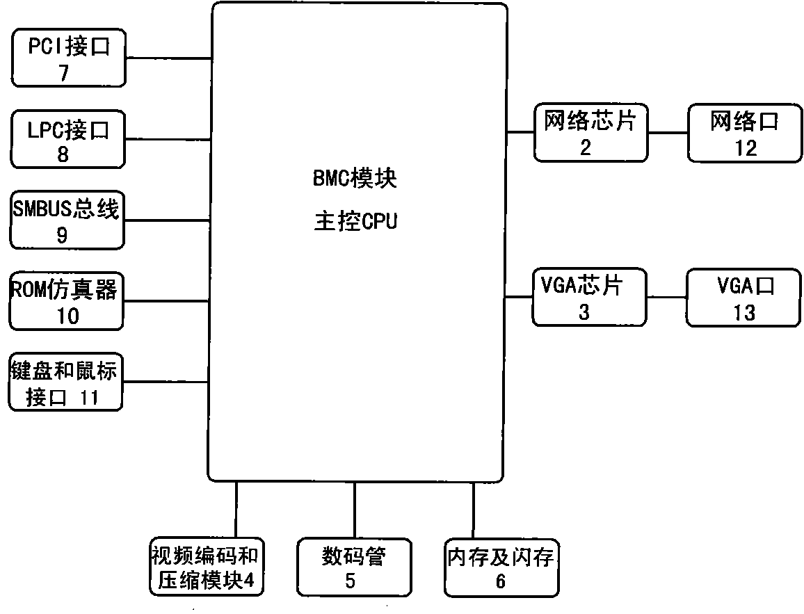
[0033] Realize the hardware structure of the inventive method as figure 1 Shown:
[0034] Main control CPU 1 of BMC module, network chip 2, VGA chip 3, video encoding and compression module 4, digital tube 5, memory and flash memory 6, PCI interface 7, LPC interface 8, SMBUS bus 9, ROM emulator 10 and keyboard and mouse interface 11 .
[0035] The BMC module is a debugging management module. Network chip 2, VGA chip 3, video encoding and compression module 4, digital tube 5, memory and flash memory 6, PCI interface 7, LPC interface 8, SMBUS bus 9, ROM emulator 10 and keyboard and mouse interface 11 are all connected with the BMC module The main control CPU 1 is connected.
[0036] The network chip 2 provides a network port 12 . The VGA chip 3 provides a VGA port 13 .
[0037] The video encoding and compression module 4 encodes and compresses the VGA signal and outputs it through the network port 12 .
[0038] Nixie tube 5 displays the debugging code.
[0039] Memory and...
Embodiment 2
[0044] Embodiment 2: (main board integration mode)
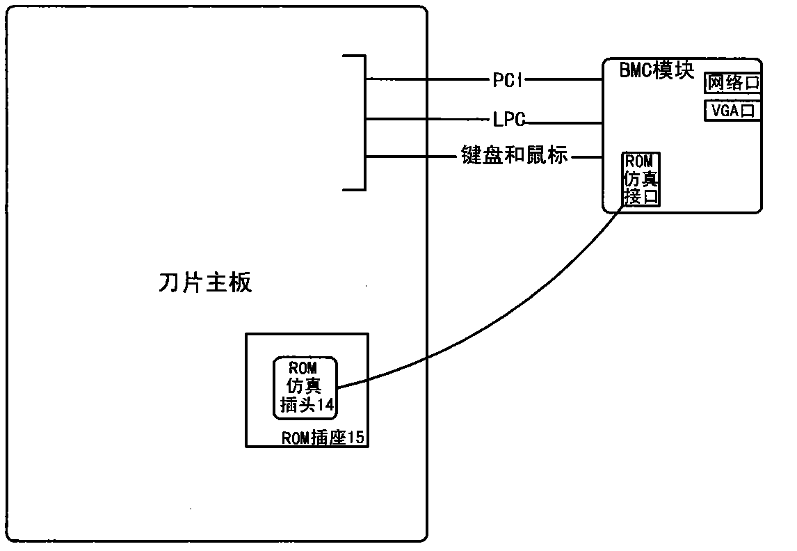
[0045] At present, the general blade server motherboards are all integrated with BMC modules, and there are PCI interfaces, LPC interfaces, keyboard and mouse interfaces between the motherboards, so it is only necessary to add a ROM emulator cable plug 14 to connect to the SPI BIOS ROM socket 15 (such as attached figure 2 shown).
Embodiment 3
[0046] Embodiment three: (separation mode)
[0047] For the case where the BMC module is not integrated in the blade server, the BMC module needs to select the PCI interface or LPC interface to connect to the blade main board, and at the same time add the ROM emulator cable plug 14 to connect to the SPIBIOS ROM socket 15 (see attached figure 2 shown).
PUM
 Abstract
Description
Claims
Application Information
 - R&D
- Intellectual Property
- Life Sciences
- Materials
- Tech Scout
- Unparalleled Data Quality
- Higher Quality Content
- 60% Fewer Hallucinations
Browse by: Latest US Patents, China's latest patents, Technical Efficacy Thesaurus, Application Domain, Technology Topic, Popular Technical Reports.
© 2025 PatSnap. All rights reserved.Legal|Privacy policy|Modern Slavery Act Transparency Statement|Sitemap|About US| Contact US: help@patsnap.com


