Travel limiting device

A travel limit and limit device technology, applied in the field of limit devices, can solve the problems of poor reliability, damage to micro switches, overload damage to components such as motors, and achieve improved work reliability, complete system functions, and reliability. The effect of the limit buffer function

Inactive Publication Date: 2013-08-21
CHINA NORTH VEHICLE RES INST
View PDF0 Cites 2 Cited by
  • Summary
  • Abstract
  • Description
  • Claims
  • Application Information

AI Technical Summary

Problems solved by technology

[0002] At present, some special vehicles install corresponding mechanical limit blocks to force the system to stop at the required position in order to realize the predetermined rotation limit of pitching parts. However, a single mechanical limit may cause overload damage to motors and other components.
Some components have built-in micro-switches, which can be in-position indication, but due to insufficient protection of the micro-switches, the micro-switches are easy to cause damage when the system works under high-speed impact conditions, and the reliability deteriorates. It is difficult to meet the work and debugging requirements under complex conditions

Method used


Image

  • Travel limiting device
  • Travel limiting device
  • Travel limiting device

Examples


Embodiment 1

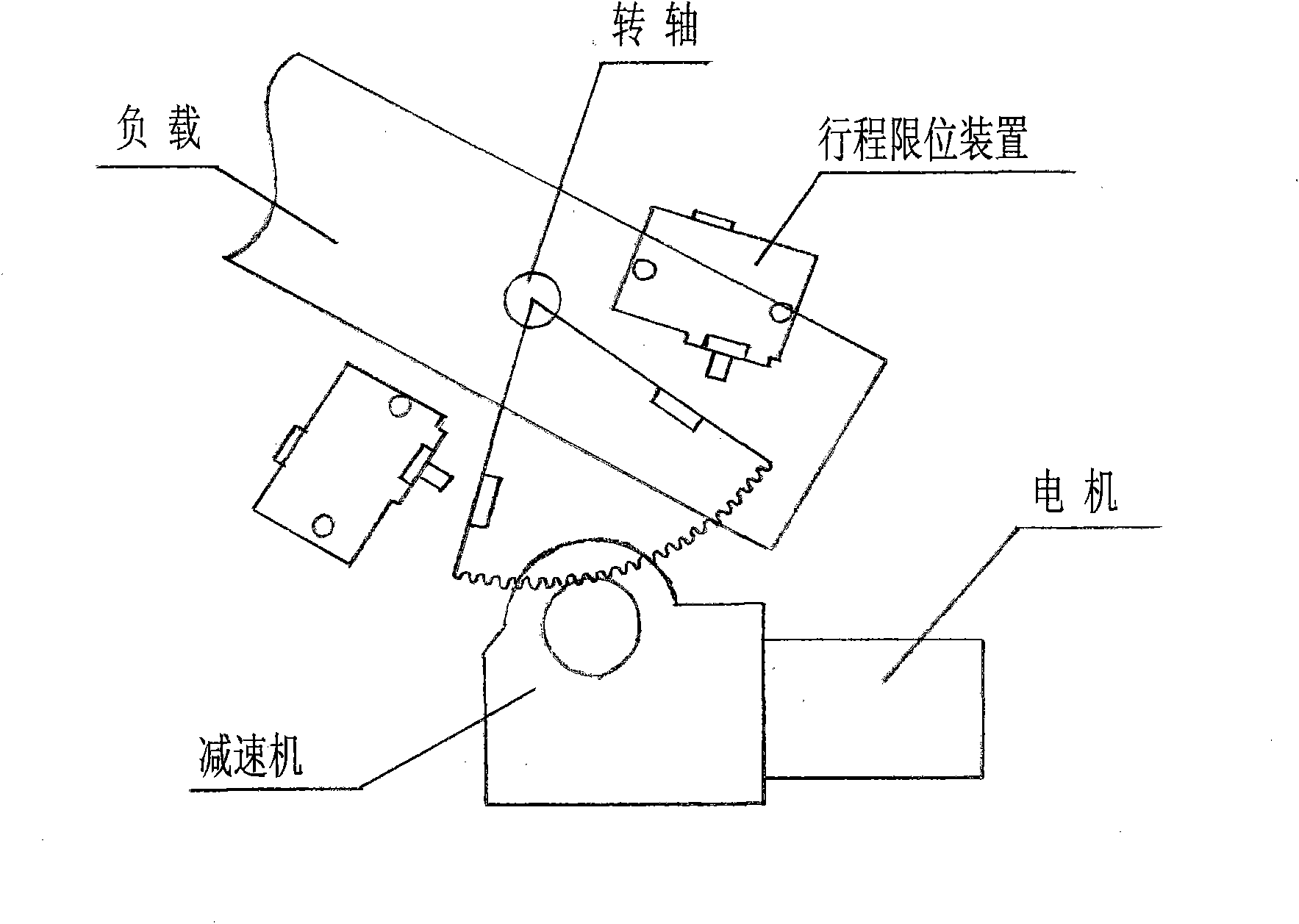
[0035] The overall structure diagram of the travel limit device of this embodiment when it cooperates with other components is as follows figure 1 As shown in the figure, the travel limit device, the rotating shaft, the motor and the reducer are all installed on the platform, the load is fixed on the platform through the rotating shaft, and the pitching motion can be performed. The motor drives the reducer to rotate and passes the gear on the reducer and the load on the The tooth arc plate teeth mesh. When the load rotates to a predetermined angle under the action of the motor and the reducer, it connects with the spring stroke shaft of the new stroke limit device. When it continues to move, the spring stroke shaft is compressed by external force. Under the action of its internal mechanism, the first trigger The microswitch contacts give an electrical signal indicating that the load is in place, and the drive motor controller cuts off the power to the motor. The load continue...

Embodiment 2

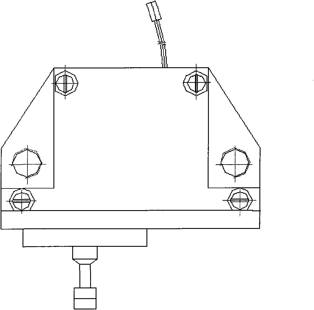
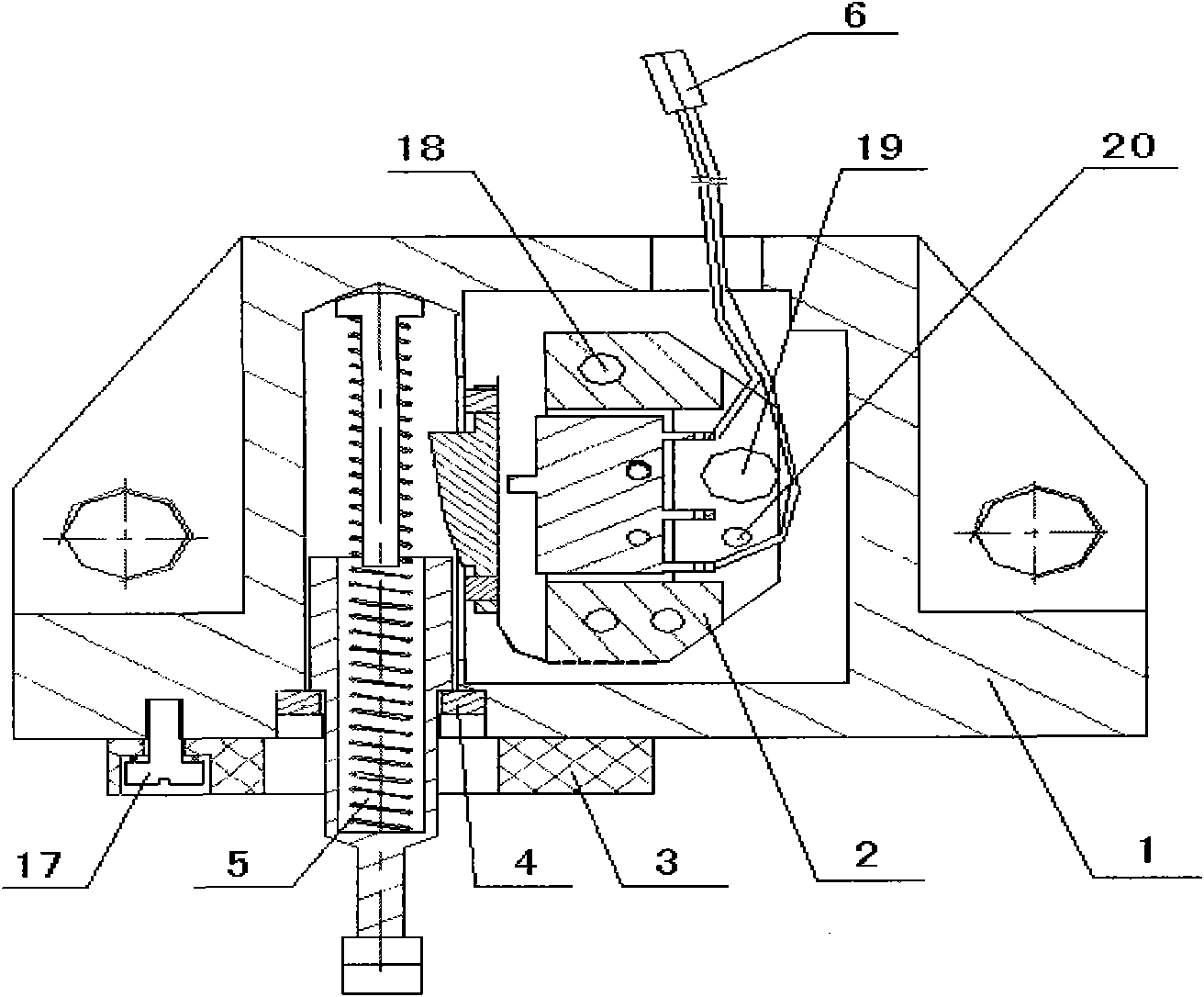
[0037] The specific structure of the stroke limiting device in this embodiment is as follows: Figure 2-6 Shown: mechanical limit Implementation: the limit switch box 1 is a carrier for component installation, the rubber pad 3 is installed on the side of the limit switch box through screws 17, and the rubber material is hard rubber.

[0038]Electric limit implementation: the spring travel shaft 5 and the travel control switch 2 are the two main assemblies for implementing the electric limit. The spring travel shaft 5 is fixed by the face plate nut 4 and the long cylindrical hole on the side of the limit switch box 1. The hollow shaft 15 can be freely extended and retracted in the cylindrical hole. The face plate nut 4 is an external thread ring structure, and the limit switch box 1. Match with the internal thread on the top. The central shaft 13 is placed inside the spring 14 , and the spring 14 is placed inside the hollow shaft 15 . When the hollow shaft 15 is compressed, i...


PUM


Abstract

The invention relates to a travel limiting device, which is characterized in that: all components of the system are arranged in a limit switch box; a working face of the limit switch box is provided with rubber plates meeting the requirements on thickness and materials so as to reasonably buffer inertial impact force applied during mechanical limit; the working face of the limit switch box is inwards provided with cylindrical cavity holes serving as access ways of a spring travel shaft; the spring travel shaft comprises a spring, a hollow shaft of which an inner cavity at one end is provided with holes, two adjusting nuts and a spring guiding shaft; and in the limit switch box, the right side of the spring travel shaft is provided with a travel control switch which comprises four components, namely a substrate, a spring piece, a flange plate and a micro switch, wherein the flange plate is arranged on the spring piece; and the micro switch and the spring piece are arranged on the substrate. The device provides effective measures for electrical limit and mechanical limit, and simultaneously effectively realizes the accurate adjustment of the positions of the electrical limit and themechanical limit by adopting the travel-length mechanical structure adjustment technology.

Description

[Technical field] [0001] The present invention relates to mechanical devices, in particular, to limit devices. [Background technique] [0002] At present, some special vehicles install corresponding mechanical limit blocks to force the system to stop moving at the required position in order to achieve the predetermined high and low angle rotation limit of the pitching components, but a single mechanical limit may cause overload damage to the motor and other components . Some components have built-in micro switches, which can indicate in-position. However, due to insufficient protection of the micro switches, the micro switches are easily damaged when the system works under high-speed shock conditions, and the reliability is deteriorated. It is difficult to meet the work and debugging requirements under complex conditions. [Content of the Invention] [0003] The purpose of the present invention is to provide a travel limit device in view of the above-mentioned defects in ...

Claims


Application Information

Patent Timeline
Patent Type & Authority Patents(China)
IPC IPC(8): H01H3/16
Inventor 钟险峰王金梅庞晓宾
Owner CHINA NORTH VEHICLE RES INST
Why Eureka
Try Eureka