Honeycombed body with a connection free area

A honeycomb, zone technology for catalyst supports, machines/engines, transportation and packaging

Active Publication Date: 2012-12-12
VTESCO TECH GMBH
View PDF0 Cites 0 Cited by
  • Summary
  • Abstract
  • Description
  • Claims
  • Application Information

AI Technical Summary

Problems solved by technology

[0006]Although various proposals have been given for designing such brazing patterns, none of them has the durability to withstand all current conditions

Method used


Image

  • Honeycombed body with a connection free area
  • Honeycombed body with a connection free area
  • Honeycombed body with a connection free area

Examples


Embodiment Construction

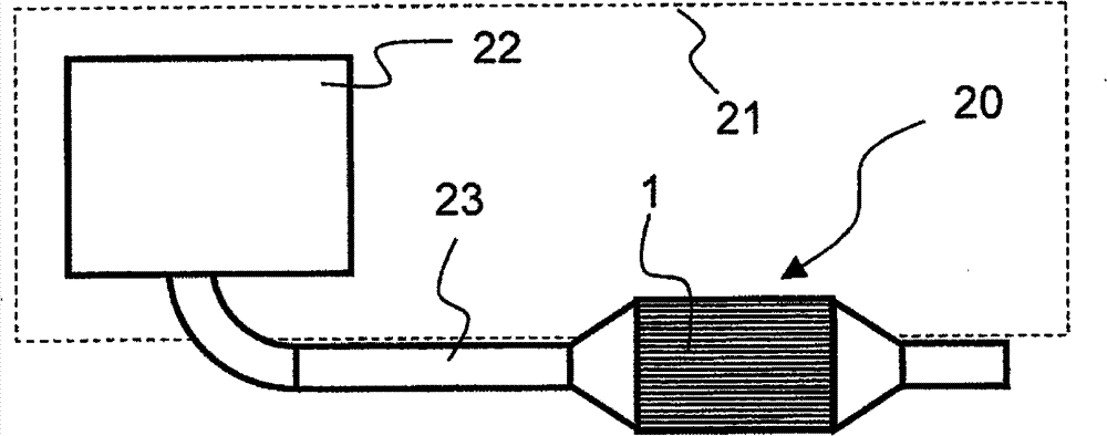
[0031] figure 1 The configuration of an on-board exhaust system of a motor vehicle 21 is schematically shown. The motor vehicle 21 has an engine 22 , for example a spark ignition engine or a compression ignition engine. The fuel combusted in the engine 22 is led as exhaust gas to the exhaust gas treatment unit 20 via a corresponding exhaust pipe 23 . In the exhaust gas treatment unit 20 , the harmful substances contained in the exhaust gas are at least partially converted and / or recirculated, so that in the end only relatively harmless exhaust gas components flow into the surroundings. Obviously, in this exhaust system, the number, type and / or location of such exhaust treatment units 20 can be changed according to various aspects (factors). A possible embodiment of the honeycomb body 1 shown in the figure is located in the exhaust pipe 23 .

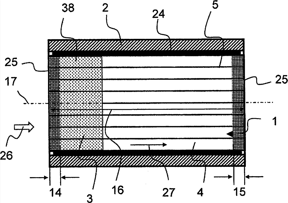
[0032] For example from figure 2 The structure of the honeycomb body 1 can be seen. figure 2 is a longitudinal section of the (c...


PUM


Abstract

A honeycomb body includes at least a housing and a honeycomb structure having a plurality of channels. The honeycomb structure is formed of at least one at least partially structured metallic layer that forms connecting points fixing the honeycomb structure. At most 20% of inner contact points in a cross section of the honeycomb structure form a connection point, and the connection points are disposed at a distance from each other in such a way that respective connection-free regions of the same size surround each of the connection points. An exhaust-gas purification unit and a motor vehicle are also provided.

Description

technical field [0001] The invention relates to a honeycomb body having at least one shell and a honeycomb structure with a plurality of channels, wherein the honeycomb structure is formed by an at least partially structured metal layer forming a fixed Connection points of the honeycomb structure. In this case, in a cross-section of the honeycomb structure, at most 20% of the internal contact points form connection points. Such honeycomb bodies, which are distinguished by their high internal flexibility, are used in particular as catalyst carriers in the exhaust system of vehicle engines. Background technique [0002] Honeycomb bodies in the exhaust gas purification of engines, such as compression ignition engines or spark ignition engines, have the advantage of a particularly large surface area, which ensures that the exhaust gas flowing through the honeycomb body is in very close contact with the channel walls. The surfaces substantially formed by the channel walls are g...

Claims


Application Information

Patent Timeline
Patent Type & Authority Patents(China)
IPC IPC(8): F01N3/28
CPCF01N2330/02F01N2260/10F01N3/281F01N2330/44Y10T428/1234Y02A50/20
Inventor R·布吕科W·莫斯P·希尔特K·阿尔特赫费
Owner VTESCO TECH GMBH
Why Eureka
Try Eureka