DMA transfer device

A technology of transmission device and transmission source, applied in the direction of instruments, electrical digital data processing, etc., can solve the problems of inability to achieve high speed, DMAC can not start DMA transmission, etc., to achieve the effect of high-speed writing

Inactive Publication Date: 2011-01-26
PANASONIC CORP
View PDF1 Cites 2 Cited by
  • Summary
  • Abstract
  • Description
  • Claims
  • Application Information

AI Technical Summary

Problems solved by technology

However, in these conventional look-ahead processing units 203, it is not possible to increase the speed of the first read in the process of reading to the DMA transfer source area.
[0010] In addition, in a general DMAC, the DMAC cannot start DMA transfer until the register setting (transfer source address, transfer destination address, transfer method, etc.)
That is, in the conventional advanced read processing unit, the period from the time when the host controller starts setting the DMAC to the completion of the first read of the DMA transfer source area is not subject to speed-up, and when the DMA needs to be started immediately become a problem in the system

Method used


Image

  • DMA transfer device
  • DMA transfer device
  • DMA transfer device

Examples


Embodiment approach 1

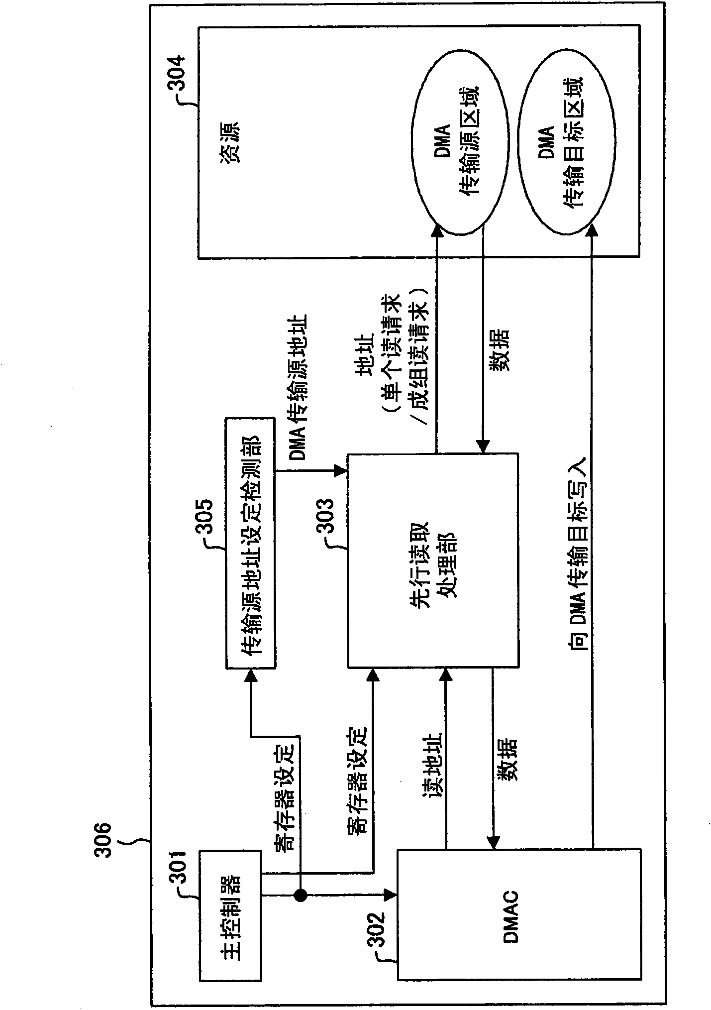
[0102] The overall structure of the DMA transmission device in this embodiment is as follows image 3 As shown, the look-ahead reading processing unit 303 in this embodiment adopts Figure 4 composition shown.

[0103] Such as Figure 4 As shown, the look-ahead processing unit 303 includes: an addition circuit 402, a look-ahead address register 403, an address selection unit 405, a look-ahead data storage buffer 406, a look-ahead read invalid register 407, a look-ahead read end address holding unit 408, a data Select section 409 . The preceding address register 403 holds addresses. The address selection unit 405 selects one of the address stored in the preceding address register 403 and the read address received from the DMAC 302 , and outputs it to the resource 304 . Data read from the resource 304 is stored in the preceding data storage buffer 406 . Data selection unit 409 selects either the data stored in preceding data storage buffer 406 or the data received from reso...

Embodiment approach 2

[0111] The overall structure of the DMA transmission device in this embodiment is as follows image 3 As shown, the look-ahead reading processing unit 303 in this embodiment adopts Figure 5 composition shown.

[0112] Such as Figure 5 As shown, the look-ahead read processing unit 303 includes: an addition circuit 502, a look-ahead address register 503, a look-ahead data storage buffer 506 capable of storing a plurality of words, a continuous look-ahead read counting section 507, and a total transfer count counting section 508 , the total transmission number holding unit 509 , and the continuous look-ahead reading number holding unit 501 .

[0113] Next, the operation of the DMA transfer device 306 in this embodiment will be described.

[0114] Upon receiving the DMA transfer source address from the transfer source address setting detection unit 305 , the preceding read processing unit 303 stores the address in the preceding address register 503 . Furthermore, the advance...

Embodiment approach 3

[0121] The overall structure of the DMA transmission device in this embodiment is as follows image 3 As shown, the look-ahead reading processing unit 303 in this embodiment adopts Figure 6 composition shown.

[0122] Such as Figure 6 As shown, the look-ahead reading processing unit 303 includes: an addition circuit 602, a look-ahead address register 603, a look-ahead data storage buffer 606, an X-direction transmission number measurement unit 607, a Y-direction transmission number measurement unit 608, and an X-direction transmission number measurement unit 608. A holding unit 609 , a Y direction transmission number holding unit 610 , and a discontinuous size holding unit 611 .

[0123] The preceding address register 603 makes a read request. The preceding data storage buffer 606 holds the read data. The X-direction transfer number measuring unit 607 counts the number of read requests. The X-direction transmission number holding unit 609 holds the upper limit of the co...


PUM


Abstract

Among register settings performed on a DMAC (302) by a master (301), a transfer source address setting detection unit (305) acquires a DMA transfer source address from the DMA transfer source region transfer start address setting. Before the DMAC (302) starts a DMA transfer, a look-ahead process unit (303) reads out data from a resource (304) specified by the DMA transfer source address and increments the DMA transfer source address, thereby repeating the look-ahead process. The DMAC (302) starts a DMA transfer upon completion of the register setting by the master (301) and reads out data from the DMA transfer source region which has been read out in advance into the look-ahead process unit (303) so as to transfer the data to the DMA transfer destination region in the resource (304).

Description

technical field [0001] The present invention relates to a DMA (Direct Memory Access) transmission device, in particular to a technique for speeding up DMA transmission by reading data from a transmission source in advance when a DMAC (Direct Memory Access Controller) performs DMA transmission. Background technique [0002] Such as figure 1 As shown, the DMA transfer device 101 is composed of a DMAC102 and a resource 103. The DMAC102 reads the DMA transfer source area on the resource 103, and writes the read data into the DMA transfer target area on the resource 103, thereby performing DMA transfer . Below, use figure 2 A conventional read-ahead technique for speeding up DMA transfer will be described. [0003] The DMA transfer device 201 includes a DMAC 202 , a look-ahead processing unit 203 , and a resource 204 . The DMAC 202 performs DMA transfer: reads the data of the DMA transfer source area on the resource 204 via the look-ahead processing unit 203 , and outputs th...

Claims


Application Information

Patent Timeline
IPC IPC(8): G06F13/28
CPCG06F13/28
Inventor 前田刚志山本大介
Owner PANASONIC CORP
Why Eureka
Try Eureka