Discharge structure of glass kiln

A glass kiln and material channel technology, applied in the direction of inorganic chemistry, non-metallic elements, halogen/halogen acid, etc., can solve the problems of increased flow, uncontrollable flow, large flow, etc., achieve low cost, facilitate promotion and operation simple effect

Active Publication Date: 2011-02-02
SHANDONG LINUO TECHNICAL GLASS CO LTD
View PDF1 Cites 0 Cited by
  • Summary
  • Abstract
  • Description
  • Claims
  • Application Information

AI Technical Summary

Problems solved by technology

[0002] During the operation of the glass furnace, due to the erosion of refractory materials and the mixing of impurities, a metamorphic layer is formed on the bottom of the kiln. This part of the bottom metamorphic glass liquid will participate in the molding if it is not removed in time, forming many defects in glass products, affecting Product quality and product pass rate
[0003] At present, the commonly used method is to drill a hole in the refractory material at the bottom of the glass kiln pool and the bottom of the forehearth, and usually seal it with a heat-resistant metal plug for intermittent discharge. The flow rate of this discharge structure cannot be controlled. It increases with the erosion of the discharge aperture, and finally leads to excessive flow and scrap
[0004] In addition, in view of the shortcomings of the traditional discharging method, some people in foreign countries wrap platinum on the refractory material to make the platinum discharging structure, and pass a current on the platinum to realize the continuous controllability of discharging by controlling the amount of power added. However, due to the price of platinum Expensive and refractory wrapped platinum is complex to process, few glass manufacturers use it

Method used


Image

  • Discharge structure of glass kiln
  • Discharge structure of glass kiln
  • Discharge structure of glass kiln

Examples


Embodiment Construction

[0021] In order to facilitate those skilled in the art to better understand the technical solution of the present invention, the present invention will be further described in detail below in conjunction with the accompanying drawings and specific embodiments.

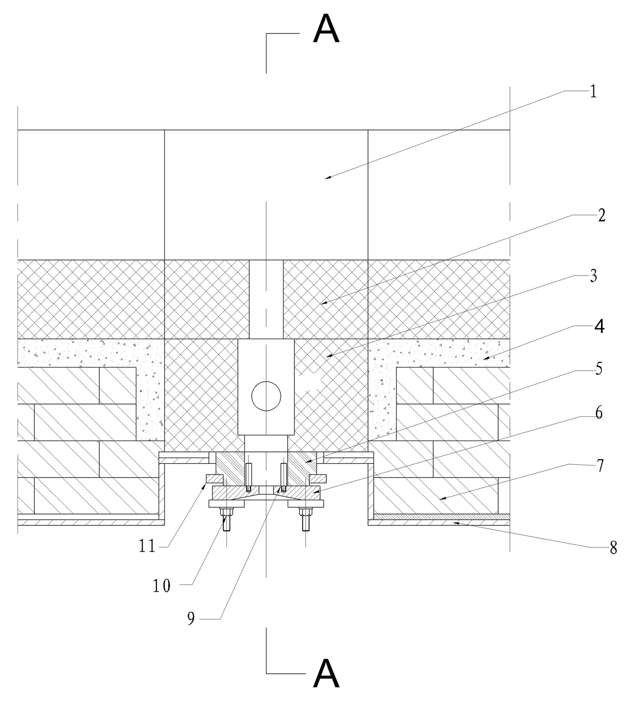
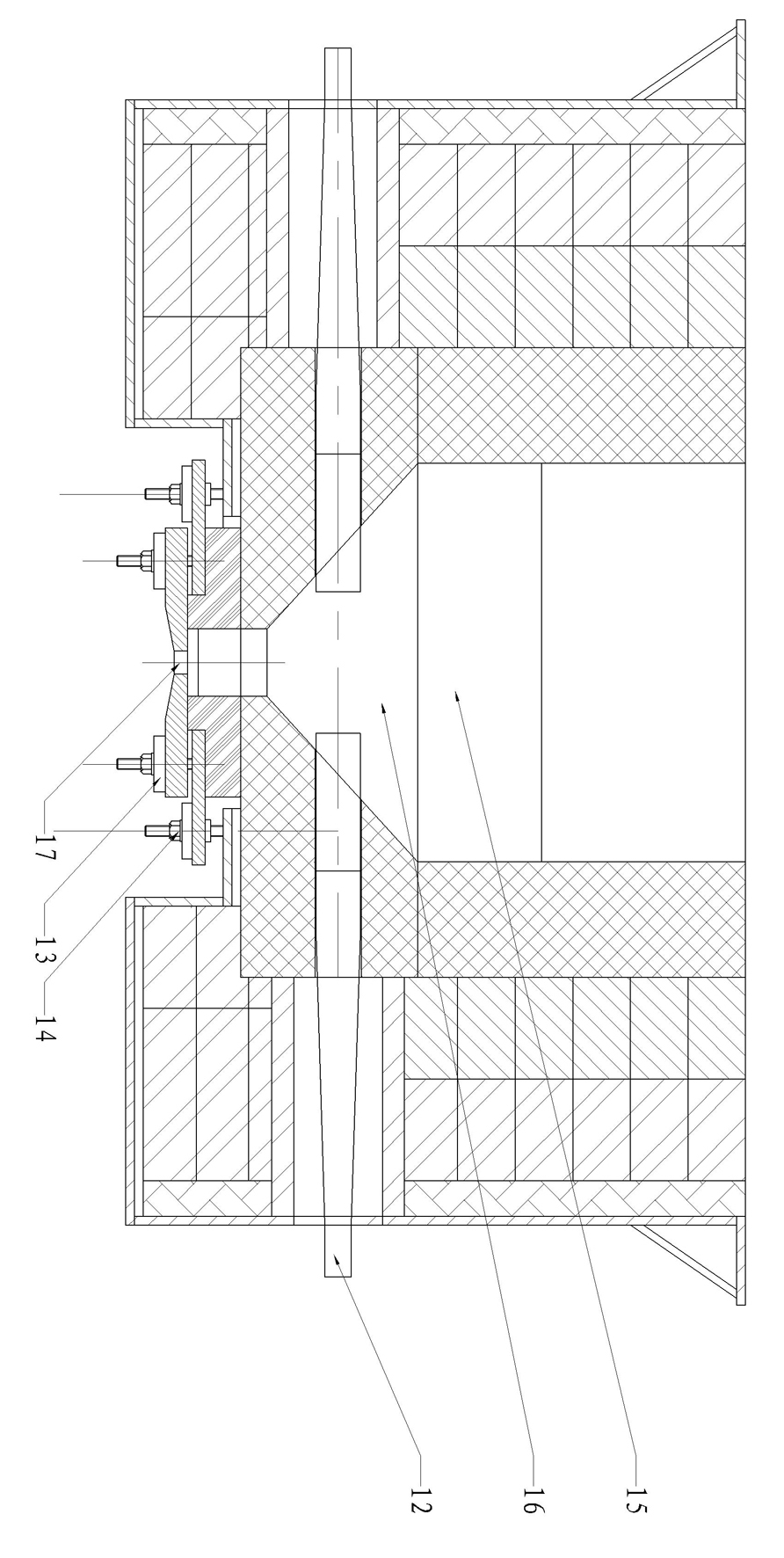
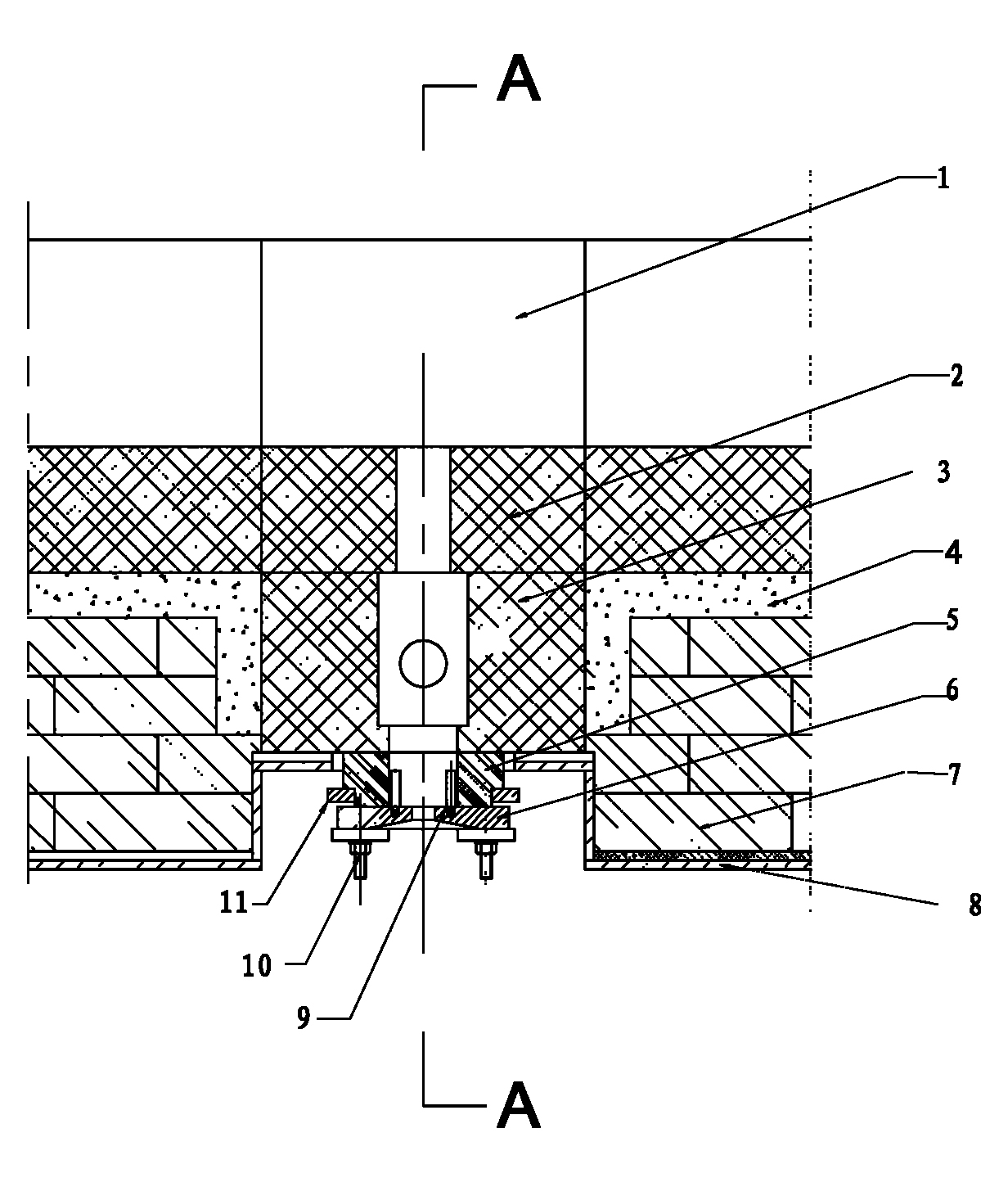
[0022] Reference attached figure 1 , 2 , a glass kiln discharging structure, the glass kiln includes a forehearth shell 8 with a discharge hole at the bottom, a forehearth 1 inside the forehearth shell 8 and a clay at the bottom of the forehearth shell 8 Brick 7, the discharge structure of the glass kiln is a cuboid structure as a whole, which includes the discharge bottom brick 2, discharge brick 3, spacer brick 5, connecting Plate 11 and heat-resistant orifice 6; the discharge bottom brick 2, discharge brick 3 and heat-resistant orifice 6 of the feedway are respectively provided with a first blanking part 15, a second blanking part 16 and a third blanking part Molybdenum electrodes 12 are installed on both sides o...


PUM


Abstract

The invention discloses a discharge structure of a glass kiln. The glass kiln comprises a material channel shell of which the bottom is provided with a discharge hole and a material channel arranged inside the material channel shell as well as a material channel discharge bottom brick, a discharge brick and a heat resistant hole plate which are sequentially arranged below the material channel from top to bottom, wherein the material channel discharge bottom brick, the discharge brick and the heat resistance hole plate are respectively provided with a first discharging part, a second discharging part and a third discharging part, and two sides of each second discharging part are provided with a molybdenum electrode; and the heat resistant hole plate is arranged below the discharge hole, and the side of the heat resistant hole plate in contact with glass liquid is provided with more than one heating rod. The invention has the advantages that degenerative glass liquid on the bottom layer of the material channel can be completely and thoroughly discharged; the main glass liquid temperature of the material channel cannot be influenced by discharging; the discharging quantity can be freely regulated and controlled as required; the structure is simple to operate and only needs remote current regulation without site operations; and the cost of the discharge structure is low, which is beneficial to the popularizing.

Description

technical field [0001] The invention relates to an electric discharge structure, in particular to a glass kiln discharge structure, which is used for a continuous and controllable high-efficiency electric discharge structure at the bottom of the material channel of the glass furnace. Background technique [0002] During the operation of the glass furnace, due to the erosion of refractory materials and the mixing of impurities, a metamorphic layer is formed on the bottom of the kiln. This part of the bottom metamorphic glass liquid will participate in the molding if it is not removed in time, forming many defects in glass products, affecting Product quality and product pass rate. [0003] At present, the commonly used method is to drill a hole in the refractory material at the bottom of the glass kiln pool and the bottom of the forehearth, and usually seal it with a heat-resistant metal plug for intermittent discharge. The flow rate of this discharge structure cannot be contr...

Claims


Application Information

Patent Timeline
Patent Type & Authority Applications(China)
IPC IPC(8): C03B7/01
Inventor 薛俊田史生宏张建忠李晔朱琪任启平许治平刘国孙庆伟
Owner SHANDONG LINUO TECHNICAL GLASS CO LTD
Why Eureka
Try Eureka