Resistor type touch key device and method for realizing resistor type touch key

An implementation method, resistive technology, applied in the direction of electrical components, electronic switches, electrical digital data processing, etc., can solve the problems of inability to guide light, high cost of light guide plates, and poor user experience, so as to save PCB area and improve anti-interference capacity, PCB area reduction effect

Active Publication Date: 2011-02-02
湃勒斯智能科技(山东)有限公司
View PDF3 Cites 4 Cited by
  • Summary
  • Abstract
  • Description
  • Claims
  • Application Information

AI Technical Summary

Problems solved by technology

At present, the commonly used touch button technologies in mobile phones generally include resistive, capacitive, etc. Under some product definitions, several touch buttons will be designed next to the touch screen; in order to realize the touch function of these buttons, an additional capacitor is added. Touch buttons have the following disadvantages: (1) Adding a capacitive touch IC will increase the cost; (2) Capacitive touch buttons are easily disturbed by the surrounding environment, so the design requires high structural space, hardware wiring and ground plane , Difficult to design; (3) The button electrode design of the capacitive touch button should be designed on the printed circuit board, and the backlight design cannot directly guide the light through the printed circuit board, and it is necessary to use a more costly light guide plate and a light-emitting LED lamp; (4) Resistive touch screen and capacitive touch button are designed together, and the user experience will be relatively poor, because the resistive touch screen needs force to trigger the touch screen function, while the capacitive touch button does not need force, only needs to be touched lightly
[0003] And if you use another resistive touch button, you need to add a touch control IC, which also increases the cost.

Method used


Image

  • Resistor type touch key device and method for realizing resistor type touch key
  • Resistor type touch key device and method for realizing resistor type touch key
  • Resistor type touch key device and method for realizing resistor type touch key

Examples


Embodiment Construction

[0028] The present invention provides a resistive touch key device and a method for realizing the resistive touch key. In order to make the purpose, technical solution and advantages of the present invention clearer and clearer, the present invention will be further described in detail below with reference to the accompanying drawings and examples. It should be understood that the specific embodiments described here are only used to explain the present invention, not to limit the present invention.

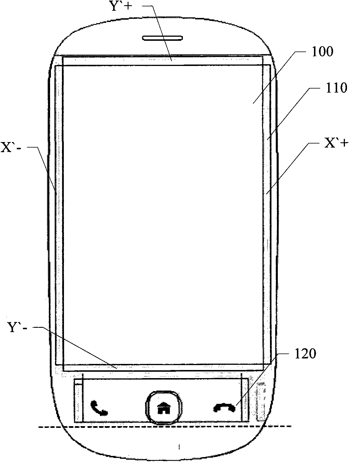
[0029] A resistive touch key device provided by an embodiment of the present invention is mainly applied in scenarios such as figure 1 As shown, the upper area is the resistive touch screen area, and the lower area is the three buttons. The bottom button in the prior art generally adopts a capacitive touch button, and a touch control IC needs to be added, which increases the cost.

[0030] Such as figure 1 As shown, the embodiment of the present invention adopts the described re...


PUM


Abstract

The invention relates to the field of touch keys, and discloses a resistor type touch key device and a method for realizing the resistor type touch key. The method comprises the following steps: A, extending coordinate electrodes at two ends of two conductive layers of a resistor type touch screen to form key electrodes; and B, distributing the key electrodes on positions corresponding to an upper circuit layer and a lower circuit layer, and adding an insulating point layer between the upper circuit layer and the lower circuit layer. A low-cost resistor type touch key is realized by extendingthe electrodes (generally silver pulp lines) of the conductive layer of the resistor type touch screen and using the principle of resistor type touch control. By adopting the device and the method, the interference resistance can be effectively improved, and because the conventional resources are used, components and parts are reduced, the PCB area is reduced, and cost is saved.

Description

technical field [0001] The invention relates to the field of touch buttons, in particular to a resistive touch button device and a method for realizing the resistive touch button. Background technique [0002] With the development of communication technology, the use of mobile phones is becoming more and more popular. At present, the commonly used touch button technologies in mobile phones generally include resistive, capacitive, etc. Under some product definitions, several touch buttons will be designed next to the touch screen; in order to realize the touch function of these buttons, an additional capacitor is added. Touch buttons have the following disadvantages: (1) Adding a capacitive touch IC will increase the cost; (2) Capacitive touch buttons are easily disturbed by the surrounding environment, so the design requires high structural space, hardware wiring and ground plane , Difficult to design; (3) The button electrode design of the capacitive touch button should be...

Claims


Application Information

Patent Timeline
Patent Type & Authority Applications(China)
IPC IPC(8): G06F3/045H03K17/96
Inventor 王亚辉
Owner 湃勒斯智能科技(山东)有限公司
Why Eureka
Try Eureka