Non-aligned row cotton stalk harvester and cotton stalk pulling harvesting table thereof

A harvesting table and harvester technology, which is applied to harvesters, agricultural machinery and implements, cutters, etc., can solve the problems of high energy consumption, large digging effect, and large wear of planers, and achieves good harvest adaptability and digging. Small effect and simple structure

Active Publication Date: 2011-11-23
CHINESE ACAD OF AGRI MECHANIZATION SCI
View PDF3 Cites 0 Cited by
  • Summary
  • Abstract
  • Description
  • Claims
  • Application Information

AI Technical Summary

Problems solved by technology

[0004] At present, common cotton stalk extraction devices include rubber roller type extraction device, vertical tooth disc extraction device, clamping type extraction device and planer roller type extraction device. The first three extraction devices cannot be misaligned due to structural limitations. Poor adaptability
Although the fourth type of extraction device, the planer roller type extraction device, achieves non-alignment extraction, it needs to penetrate 10-20 mm into the soil when it works, which has a great effect on soil excavation, high energy consumption, and relatively large wear of the soil on the planer. , the worn planer leads to serious "missing pull" phenomenon
[0005] In recent years, the research on cotton stalk harvesting machines at home and abroad has made great progress, but almost all of the research is based on cotton stalk extraction. The harvesting method of cotton stalks is basically "throwing after pulling, picking after throwing". "Segmental harvesting mode, lack of research on joint operations, and research on the arrangement of cotton stalks after pulling and the separation of cotton stalks and soil after pulling is still blank.

Method used


Image

  • Non-aligned row cotton stalk harvester and cotton stalk pulling harvesting table thereof
  • Non-aligned row cotton stalk harvester and cotton stalk pulling harvesting table thereof
  • Non-aligned row cotton stalk harvester and cotton stalk pulling harvesting table thereof

Examples


Embodiment Construction

[0078] Below in conjunction with accompanying drawing, structural principle and working principle of the present invention are specifically described:

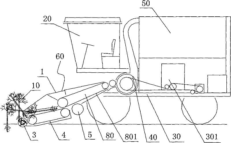
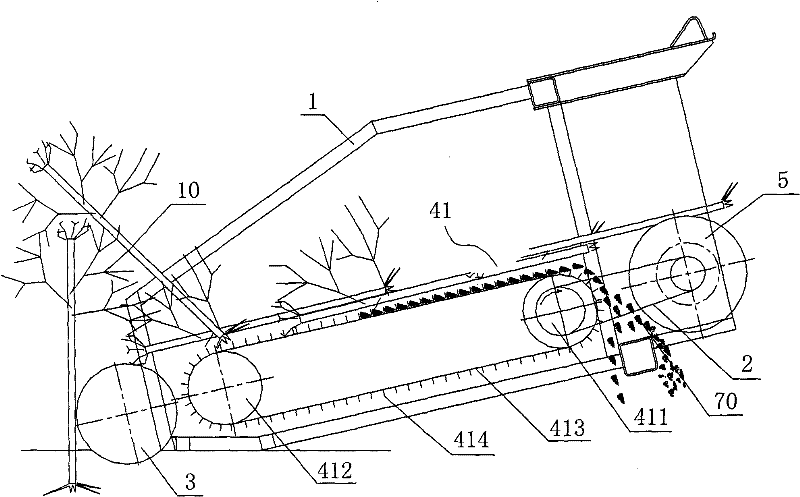
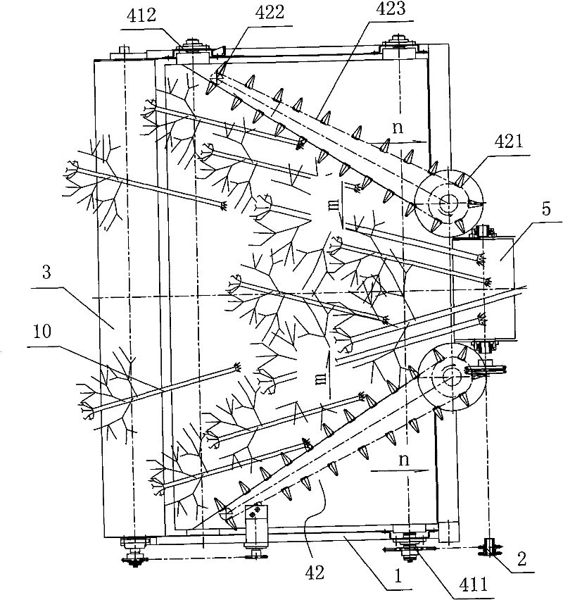
[0079] see figure 1 , figure 1 It is a structural schematic diagram of the non-aligned cotton stalk harvester of the present invention. The non-aligned cotton stalk harvester of the present invention includes a cab 20, a walking chassis 30, a cotton stalk extraction and harvesting platform 60, a conveying trough 80, a chopping device 40, and a collecting device 50. The front part above the chassis 30, the chopping device 40 and the material collecting device 50 are installed on the walking chassis 30 and set behind the driver's cab 20, and the cotton stalk extraction and harvesting platform 60 is set on the conveying The front end of the trough 80 is connected to the chopping device 40 through the conveying trough 80, the chopping device 40 is connected to the collection device 50, the cotton stalk extraction harvesting plat...


PUM


Abstract

The invention discloses a non-aligned row cotton stalk harvester and a cotton stalk pulling harvesting table thereof. The harvester comprises a cab, a travelling chassis, the cotton stalk pulling harvesting table, a mincing device and a collecting device, wherein the cab is arranged on the front part above the travelling chassis; the mincing device and the collecting device are arranged on the travelling chassis and arranged in back of the cab; the cotton stalk pulling harvesting table is arranged at the front end of the travelling chassis and connected with the mincing device; the mincing device is connected with the collecting device; the cotton stalk pulling harvesting table and the mincing device are connected with a power structure of the travelling chassis respectively; the harvesting table comprises a frame and a cotton stalk pulling device, a cotton stalk conveying device and a transmission system arranged on the frame; the cotton stalk pulling device and the cotton stalk conveying device are connected with the transmission system respectively; the cotton stalk pulling device is arranged below the front end of the cotton stalk conveying device; and the cotton stalk conveying device comprises a finishing link plate. The harvester realizes non-aligned row pulling of cotton stalks, and has good harvesting adaptability and low energy consumption.

Description

technical field [0001] The invention relates to a cotton harvesting device, in particular to a non-aligned cotton stalk harvester and a cotton stalk extraction harvesting platform. Background technique [0002] Cotton stalk harvesting is mainly harvested by plucking stalks. The main reason is that cotton stalks are hard and not easy to rot and crush, and they remain in the soil for a long time, which is not conducive to subsequent land preparation operations and crop growth, and cannot meet the agronomic requirements of "intensive farming". Cotton planting in my country mostly adopts film-laying to increase temperature and preserve moisture. The climate, soil, and varieties vary greatly across the country, and the row spacing of cotton planting is varied. Therefore, if a harvester for pulling cotton stalks in wrong rows can be developed, it will greatly increase the suitable harvest range, make full use of the geographical advantages of my country's north-south depth and len...

Claims


Application Information

Patent Timeline
Patent Type & Authority Patents(China)
IPC IPC(8): A01D45/00A01D43/08
Inventor 唐遵峰韩增德甘帮兴包春林
Owner CHINESE ACAD OF AGRI MECHANIZATION SCI
Why Eureka
Try Eureka