Speed simulator of train

A simulation device and vehicle speed technology, applied in the field of train speed simulation devices, can solve the problems such as the inability to accurately know the speed of the vehicle, the inability to accurately repeat the test of the scene, and the inability to provide data basis, etc.

Active Publication Date: 2011-02-09
HENAN SPLENDOR SCI & TECH
View PDF7 Cites 3 Cited by
  • Summary
  • Abstract
  • Description
  • Claims
  • Application Information

AI Technical Summary

Problems solved by technology

[0002] Axle counting system is used to judge the status of track occupancy / idle in many bad branch sections in the railway system. The magnetic head is the core of the axle counting system. The magnetic head is installed on the rail. When the train wheel passes above it, the iron wheel changes the magnetic head. The nearby electromagnetic field distribution enables the magnetic head to use this change to count the number of passing wheels; but with the increase of train speed, the current speed of high-speed passenger trains has reached 350km / h. When such wheels pass above the magnetic head at high speed, Whether the magnetic head can still accurately and reliably count the number of passing wheels has always been a problem that plagues axle counting equipment manufacturers
[0003] For a long time, in the speed experiment of the magnetic head in the axle counting system, many manufacturers have adopted the method of theoretical analysis to infer, but there is no actual test, and the theoretical inference cannot be confirmed. Other manufacturers have adopted the method of installing magnetic heads on actual lines and using actual trains. However, this method also has obvious shortcomings: 1. The speed of the vehicle cannot be accurately known, and the speed cannot be selected and controlled; 2. The test of the full speed point of 0-350km / h cannot be realized; 3. The tested scene cannot be accurate Repeat the test; therefore, the magnetic head tested by the aforementioned method can only analyze the general conclusion of whether the magnetic head is usable in a certain speed range from the general trend at most, and cannot give accurate data basis

Method used


Image

  • Speed simulator of train
  • Speed simulator of train
  • Speed simulator of train

Examples


Embodiment Construction

[0016] The technical solutions of the present invention will be described in further detail below through specific implementation methods.

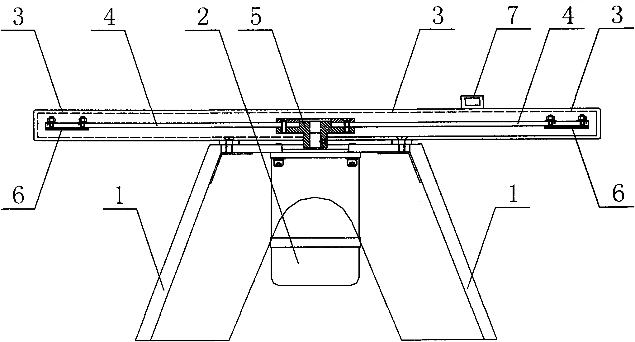
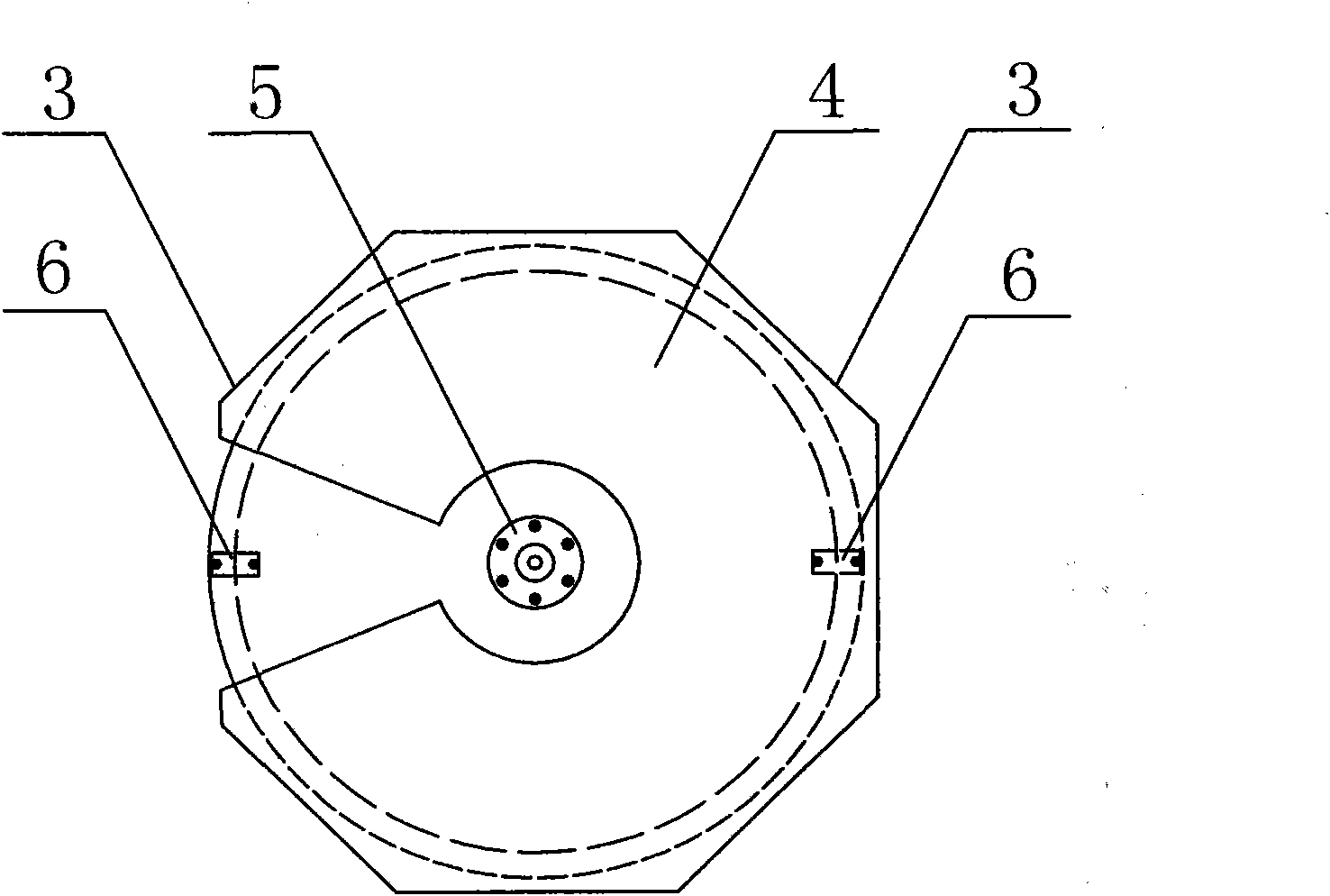
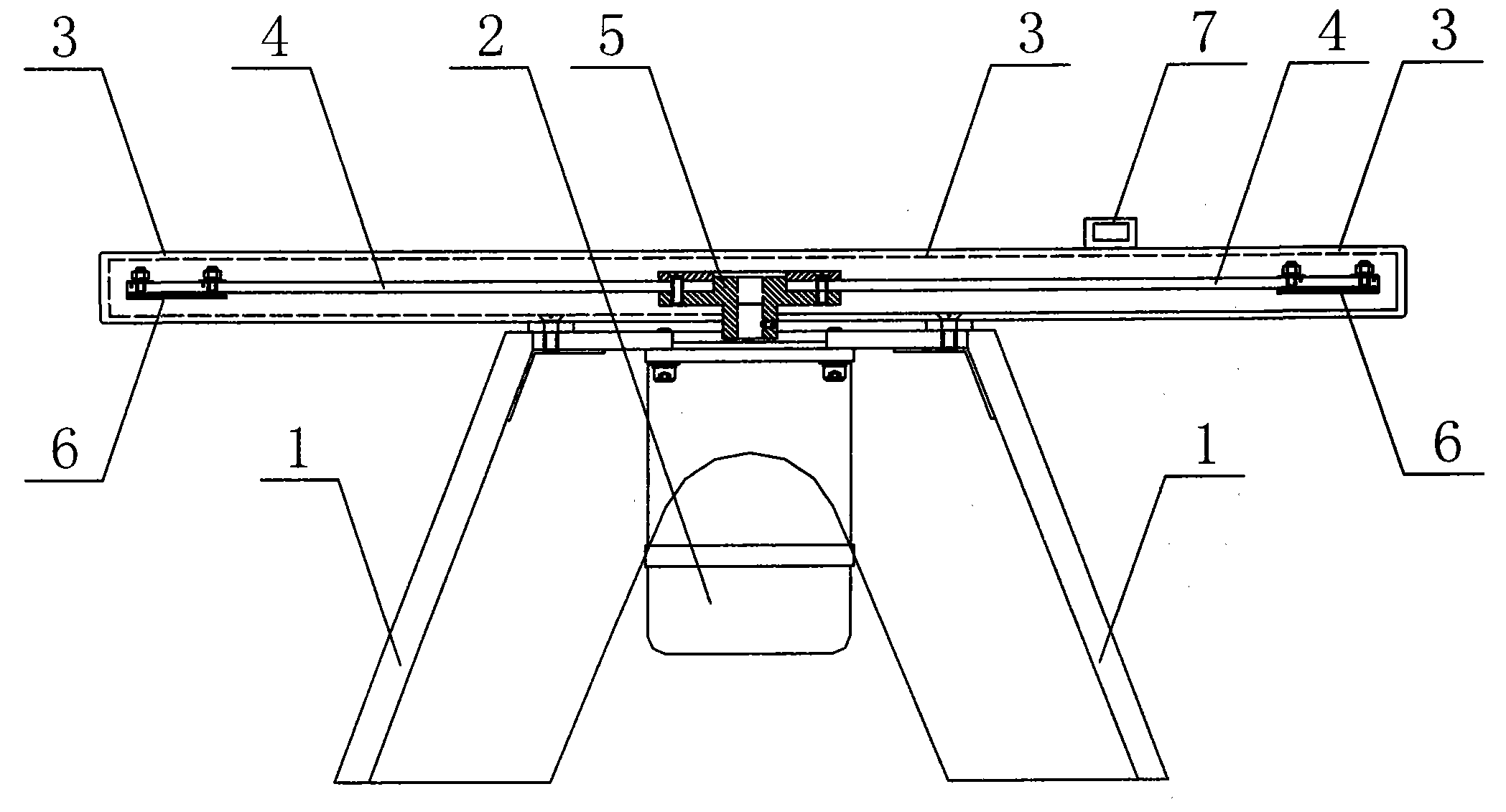
[0017] Such as figure 1 and figure 2 Shown, a kind of train speed simulation device, it comprises support 1, motor 2, protective cover 3, rotating disc 4, flange 5, tachometer 7 and two shielding sheets 6, wherein, described protective cover 3 is horizontally installed on The upper part of the bracket 1, the motor 2 is arranged at the lower part of the bracket 1, the output shaft of the motor 2 is vertically connected with the middle part of the rotating disk 4 through a group of flanges 5, and the rotating disk 4 is horizontally arranged on the Inside the protective cover 3, two shielding pieces 6 are symmetrically arranged on the lower side of the rotating disk 4, and the components of the speed detector 7 are installed on the rotating disk 4 and the protective cover 3 respectively.

[0018] Described motor 2 is a direct current moto...


PUM


Abstract

The invention provides a speed simulator of a train, which comprises a bracket, a motor, a protective cover, a rotating disk, a flange, a speedometer and two shielding sheets, wherein the protective cover is horizontally arranged on the upper part of the bracket; the motor is arranged on the lower part of the bracket; an output shaft of the motor is vertically connected with the middle part of the rotating disk through the flange; the rotating disk is horizontally arranged in the protective cover; the two shielding sheets are symmetrically arranged on the lower side of the rotating disk; and the speedometer is arranged on the rotating disk and the protective cover. The invention provides a device for simulating the train to pass through a magnetic head in a speed of 0 to 350 km / h, which ensures that a quantitative test of the speed of the magnetic head in axle counter equipment is realized; the train speed simulated by the device is continuous and adjustable; the device can safely and stably simulate the constant speed running of the train at any speed point in 0 to 350 km / h; and the difficulty that the speed test of the magnetic head in the axle counter equipment in railway cannot be carried out is solved.

Description

technical field [0001] The invention relates to a train speed simulation device, which is used for the speed test of a magnetic head in a railway axle counting system and belongs to the technical field of railway signals. Background technique [0002] Axle counting system is used to judge the status of track occupancy / idle in many bad branch sections in the railway system. The magnetic head is the core of the axle counting system. The magnetic head is installed on the rail. When the train wheel passes above it, the iron wheel changes the magnetic head. The nearby electromagnetic field distribution enables the magnetic head to use this change to count the number of passing wheels; but with the increase of train speed, the current speed of high-speed passenger trains has reached 350km / h. When such wheels pass above the magnetic head at high speed, Whether the magnetic head can still accurately and reliably count the number of passing wheels has always been a problem that has p...

Claims


Application Information

Patent Timeline
Patent Type & Authority Applications(China)
IPC IPC(8): B61L1/16
Inventor 张成斌黄利华云振东
Owner HENAN SPLENDOR SCI & TECH
Why Eureka
Try Eureka