Permanent magnetic DC incremental motor

A motor, permanent magnet technology, applied in the direction of electrical components, electromechanical devices, etc., can solve the problems of large size and difficulty in stepless speed change, and achieve the effect of small size, light weight and high power

Inactive Publication Date: 2003-10-08
邱兆云
View PDF0 Cites 0 Cited by
  • Summary
  • Abstract
  • Description
  • Claims
  • Application Information

AI Technical Summary

Problems solved by technology

If you want to output linear motion, you can only add a transmission mechanism
In addition, it is quite difficult to realize stepless transmission, and its volume is generally large.

Method used


Image

  • Permanent magnetic DC incremental motor
  • Permanent magnetic DC incremental motor
  • Permanent magnetic DC incremental motor

Examples


Embodiment Construction

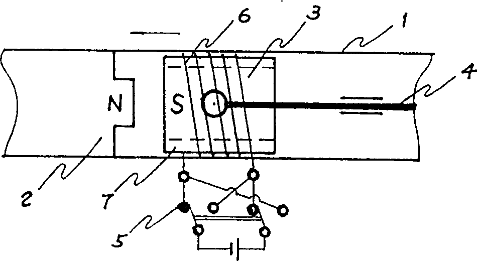
[0016] figure 1 As shown, Embodiment 1 is composed of a machine base 1 , a stator 2 , an armature 3 , an output shaft 4 and a commutator 5 . The stator 2 consists of permanent magnets. The corresponding armature 3 consists of an electromagnet. The electromagnet consists of a bobbin 7 and a conductive coil 6 . The output shaft 4 is installed on the coil frame 7 . The commutator 5 is composed of a reversing switch circuit, and its two poles are connected with the two poles of the conductive coil 6 .

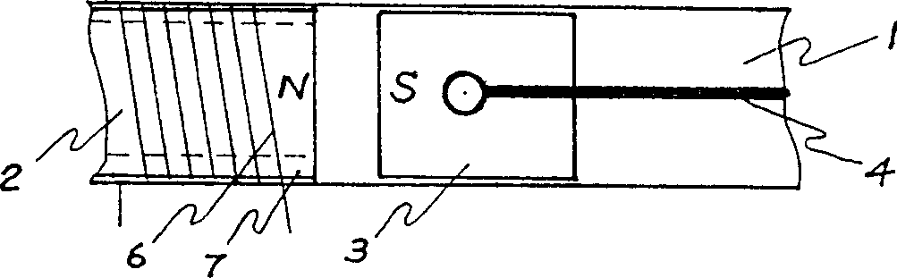
[0017] figure 2 Shown, the stator 2 of embodiment 2 is made up of an electromagnet. Armature 3 consists of a permanent magnet. The electromagnet consists of a bobbin 7 and a conductive coil 6 .

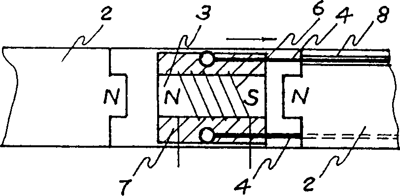
[0018] image 3 As shown, the stator 2 of Embodiment 3 is composed of two permanent magnets on the left and the right. Armature 3 consists of an electromagnet. The electromagnet consists of a bobbin 7 and a conductive coil 6 . The conductive coil 6 is located at the center of t...


PUM


Abstract

The present invention relates to a permanent-magnet D.C. incremental motor, which comprises machine seat, stator, armature, output shaft and commutator, one of stator and armature is made of permanent-magnet, and its correspondent another component is made of electromagnet. The electromagnet is formed from coil frame and conductive coil, said conductive coil is connected with two poles of the commutator. Its ouput shaft can output linear movement, also can output rotary movement by means of crank-guide mechanism. The stator can be made of two permanent-magnets or electromagnets, and its correspondent armature comprises one electromagnet or permanent-magnet. Its structure is simple, output power and rotating speed can be continuously regulated so that it can be extensively used in the design and manufacture of electromechanical products.

Description

technical field [0001] The invention relates to the design and manufacture of a motor, more specifically an improvement of a permanent magnet DC incremental motor with simple structure and capable of outputting both linear motion and rotary motion. Background technique [0002] Most of the traditional permanent magnet DC motors have a complex structure, consisting of a base, a stator, an armature, a motor shaft, a commutator, and brushes. The coil windings are intricate, and the armature and commutator are also complicated. The complex structure will inevitably lead to complex processing technology, increased manufacturing costs and reduced reliability, making the parts vulnerable to damage and difficult to maintain. The stator of the traditional permanent magnet DC motor is fixed, the rotor rotates, and the output shaft can only output rotary motion. If you want to output linear motion, you can only add a transmission mechanism. In addition, it is quite difficult to real...

Claims


Application Information

Patent Timeline
Patent Type & Authority Patents(China)
IPC IPC(8): H02K33/18
Inventor 邱兆云
Owner 邱兆云
Why Eureka
Try Eureka