Intelligent warp-knitting-machine needle-bed headstock speed-range variable motion system

A warp knitting machine needle and kinematic system technology, applied in the field of warp knitting machines, can solve problems such as unadjustable movement speed and amplitude of the ejector rod, long auxiliary time, and affecting the effective working time of the warp knitting machine, and achieve undulating speed and continuous stroke Effects of adjustable, reduced labor and maintenance costs, and elimination of lubricating oil contamination problems

Inactive Publication Date: 2018-07-13
常州源通电子科技有限公司
View PDF0 Cites 0 Cited by
  • Summary
  • Abstract
  • Description
  • Claims
  • Application Information

AI Technical Summary

Problems solved by technology

[0002] The warp knitting machine is a textile equipment for special fabrics. In the warp knitting machine, the swing of each needle bed is driven by a cam with a specific shape line to change the lifting speed of the tappet. The patterns of different specifications need corresponding cams. Realization, due to the e

Method used


Image

  • Intelligent warp-knitting-machine needle-bed headstock speed-range variable motion system
  • Intelligent warp-knitting-machine needle-bed headstock speed-range variable motion system
  • Intelligent warp-knitting-machine needle-bed headstock speed-range variable motion system

Examples


Embodiment Construction

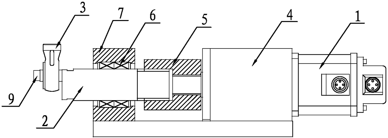
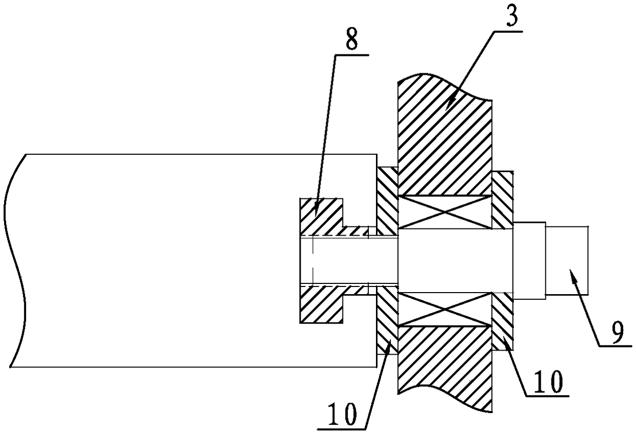
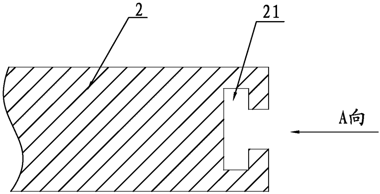
[0031] An intelligent warp knitting machine needle bed ejector rod variable speed variable range motion system, such as Figure 1-5 As shown, it includes a variable speed motor 1, a rotating shaft 2, a needle bed tappet seat 3, a reducer 4, a coupling 5, a main shaft bearing 6, a bearing seat 7, a slider 8, a locking mandrel 9 and an axial gasket 10 The variable speed motor 1 drives the rotating shaft 2 through the reducer 4 and the shaft coupling 5, and the rotating shaft 2 is installed on the bearing seat 7 through the main shaft bearing 6. The variable speed motor 1 is a DC frequency conversion motor, and the needle bed tappet seat 3 is adjusted radially The device is installed on the extended end of the rotating shaft 2, and the radial position of the needle bed tappet seat 3 along the rotating shaft 2 can be adjusted. The slider 8 corresponding to the groove 21 and the locking mandrel 9, the slider 8 is sleeved in the radial chute 21 of the rotating shaft 2, and an intern...


PUM


Abstract

Disclosed is an intelligent warp-knitting-machine needle-bed headstock speed-range variable motion system which comprises a variable speed motor, a rotating shaft and a needle bed plunger cap. The variable speed motor drives the rotating shaft, the needle bed plunger cap is mounted on the extension end of the rotating shaft through a radial regulating device, and the needle bed plunger cap is radially adjustable along the rotating shaft. Output of kinetic energy is achieved in the motion mode that the variable speed motor drives an eccentric wheel with adjustable eccentric distance to move, sothat traveling trajectory of a needle bed swinging cam of a warp knitting machine is flexibly variable; driving on a plunger does not rely on the travelling cam, so that the plunger does not contactwith the cam directly; lateral force does not exist since the plunger is only subjected to axial force, motion resistance is greatly lowered, abrasion of the plunger is avoided, a plunger driving mechanism does not need to be dipped in an oil groove, and the problem about lubricant pollution commonly existing in the warp knitting machine is solved.

Description

technical field [0001] The invention relates to the field of warp knitting machines, in particular to a motion control system for simulating a main shaft of a warp knitting machine. Background technique [0002] The warp knitting machine is a textile equipment for special fabrics. In the warp knitting machine, the swing of each needle bed is driven by a cam with a specific shape to change the lifting speed of the tappet. Different specifications of patterns need corresponding cams to adjust the speed of the tappet. Realization, due to the ever-changing specifications and shapes of lace cloth, in order to meet the production needs, it is not only necessary to be equipped with many specifications of cams, but also to manually replace them, which not only increases the production cost, but also directly affects the effective working time of the warp knitting machine. In recent years, the applicant has been researching the swing mechanism of the needle bed of the warp knitting m...

Claims


Application Information

Patent Timeline
IPC IPC(8): D04B27/08
CPCD04B27/08
Inventor 臧玉柱孙正林鲍家龙臧磊
Owner 常州源通电子科技有限公司
Why Eureka
Try Eureka