Flow guide gate

A deflector and arm body technology, which is applied in the field of diversion doors, can solve the problems of small working width and inconvenient disassembly and assembly of diversion doors, and achieve the effects of increasing the working width, good passability, and improving collection efficiency

Active Publication Date: 2011-02-09
VISIONNAV ROBOTICS SHENZHEN LTD
View PDF5 Cites 0 Cited by
  • Summary
  • Abstract
  • Description
  • Claims
  • Application Information

AI Technical Summary

Problems solved by technology

[0003] In order to overcome the inconvenient disassembly and assembly of the existing flow diversion door, and its working width is generally very small, the present invention provides a flow diversion door

Method used


Image

  • Flow guide gate
  • Flow guide gate
  • Flow guide gate

Examples


Embodiment Construction

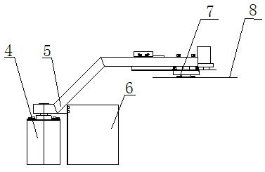
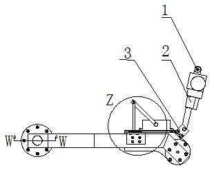
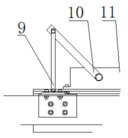
[0015] A deflector door, including a rear support shaft 1, an electric push rod 2, a connecting seat 3, a nylon brush 4, a deflector arm body 5, a deflector plate 6, a buffer support 7, a deck 8, a connecting rod 9, and a crank 10. Rotating buffer 11, connection block 12, transmission barrel 13 and built-in motor 14.

[0016] Such as figure 1 It is a structural schematic diagram of the present invention, a diversion door, including a push-pull module, a buffer module, a rotation module and a deflector plate, the push-pull module is composed of an electric push rod 2, a connecting seat 3 connected with the electric push rod 2 and a rear support Shaft 1, the buffer module is composed of a buffer support 7, a rotating buffer 11 fixed on the buffer support 7, a crank 10 and a connecting rod 9, and the rotating module is composed of a connecting block 12 located at the front end of the guide arm body 5 , a built-in motor 14, a transmission barrel 13 and a nylon brush 4, the deflec...


PUM


Abstract

The invention relates to a flow guide gate relating to the technical field of lake surface cleaning ships. The flow guide gate comprises a push-and-pull module, a buffer module, a rotating module and a flow guide plate, wherein the push-and-pull module comprises an electric push rod, a connecting seat and a rear supporting shaft, wherein the connecting seat is connected with the electric push rod; the buffer module comprises a buffer support, a rotating buffer, a crank and a connecting rod; the rotating module comprises a connection block, a built-in motor, a transmission barrel and a nylon brush, wherein the connection block is positioned on the front end of a flow guide arm body; and the flow guide plate is fixed on the flow guide arm body and positioned at the rear side of the nylon brush. The device increases the operation width and also gathers the rubbishes positioned on a water surface to an effective position, thereby greatly enhancing the collection efficiency; and in addition, the nylon brush can complete the work, i.e. revetment cleaning and the like which are difficult to complete by the traditional cleaning device. The buffer module plays a role of protecting the flow guide gate; and the push-and-pull module controls the opening and closing angle of the flow guide arm body, therefore the flow guide gate can not only provide an optimal upstream face during normal work, but also achieves good through capacity in a complex water area.

Description

technical field [0001] The invention relates to the technical field of lake surface cleaning boats, in particular to a diversion door. Background technique [0002] At present, people pay more and more attention to the protection of the environment, including the protection of water sources. In order to keep the water surface clean, salvage ships for cleaning water surface garbage are equipped in coastal ports, inland rivers and lakes. The bow of the salvage ship is provided with diversion doors, so that a runner inlet can be formed in front of the garbage collection mechanism, so that the surface garbage in the front of the runner mouth and the accessories are guided into the garbage collection mechanism. Wherein the diversion door is located at the bow, the existing diversion door not only uses a lot of materials, is heavy, has high manufacturing cost, and is inconvenient to disassemble, therefore, it is very difficult to repair and replace the diversion door, and its Th...

Claims


Application Information

Patent Timeline
Patent Type & Authority Applications(China)
IPC IPC(8): E02B15/04
Inventor 刘云辉陆波宋宝泉杨延光刘顺韩宇
Owner VISIONNAV ROBOTICS SHENZHEN LTD
Why Eureka
Try Eureka