Pipe flow and jet grouting compound energy generator

A generator and pipe flow technology, which is applied in the field of pipe flow rotary jet regenerating generators, can solve the problems that restrict the popularization and application of hydropower technology among the people, the application range is not wide enough, and hydropower cannot be used in water-deficient areas, etc., and it is easy to promote , low cost, small footprint

Inactive Publication Date: 2013-03-20
王治岳
View PDF9 Cites 1 Cited by
  • Summary
  • Abstract
  • Description
  • Claims
  • Application Information

AI Technical Summary

Problems solved by technology

However, the existing hydroelectric power generation devices are generally installed on large rivers, and use the water flow drop to generate power. Although they can generate powerful electric energy, their application range is not wide enough. Many water-deficient areas cannot carry out hydropower generation, which restricts hydropower generation. Popularization and application of technology to the people

Method used


Image

  • Pipe flow and jet grouting compound energy generator
  • Pipe flow and jet grouting compound energy generator

Examples


Embodiment Construction

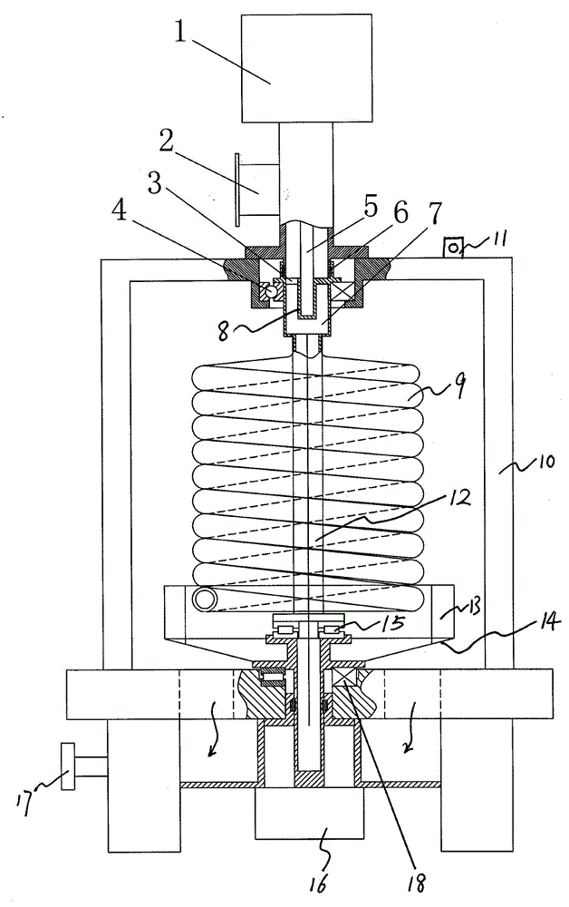
[0010] A kind of tube-flow swirl-jet compound energy generator, such as figure 1 , figure 2 As shown, it includes a closed casing 10 and a generator, the generators are two sets of upper and lower generators, and the upper generator 1 is vertically installed on the top of the water inlet pipe 2 in the center of the top surface of the closed casing, and the water inlet pipe 2 is connected with the water source or the high-pressure water pump. Connected, the lower part of the water inlet pipe 2 is connected to the center of the top surface of the housing 10 by a flange, and the lower generator 16 is vertically installed at the center of the bottom surface of the housing 10 .

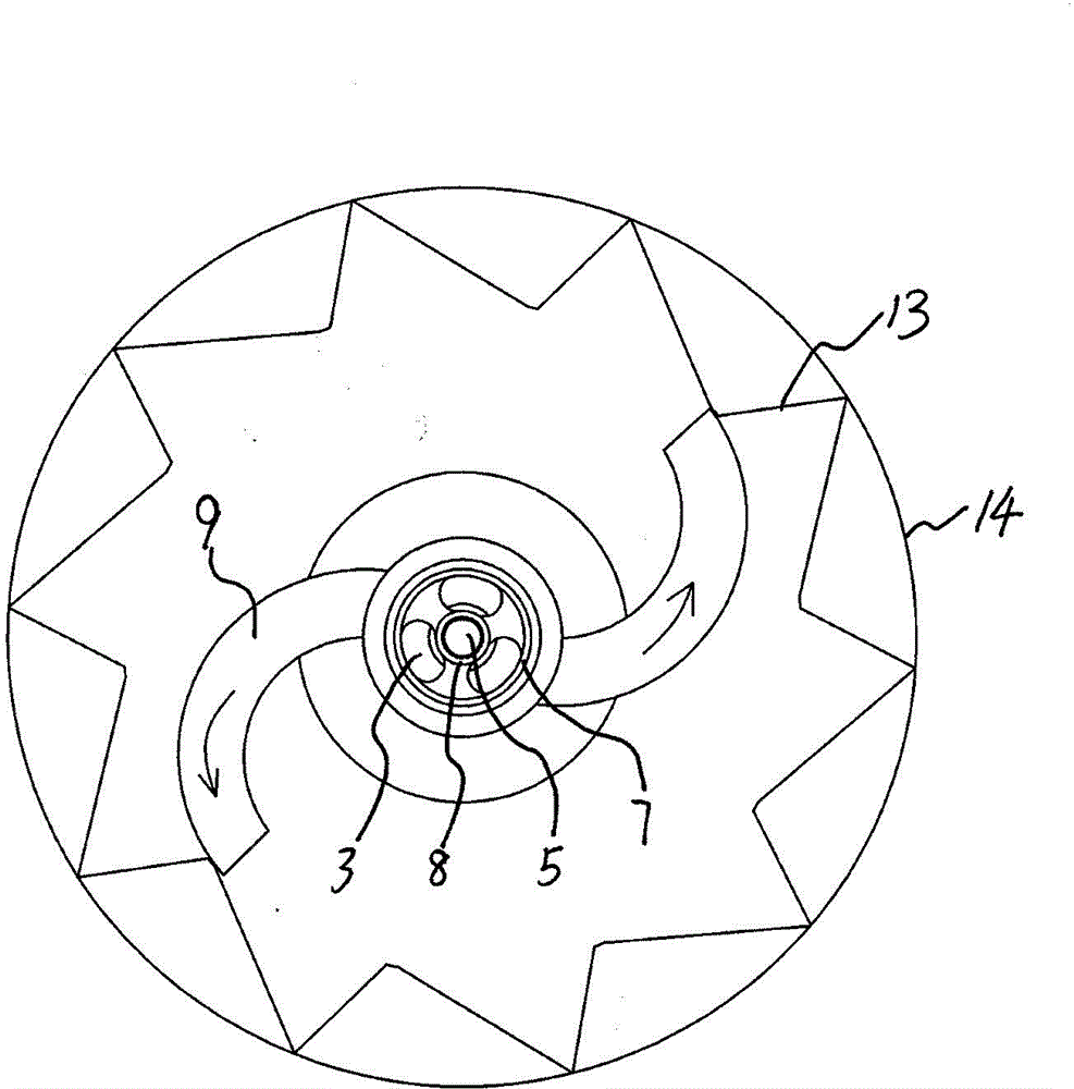
[0011] Such as figure 1 , figure 2 as shown, A rotating water pipe assembly 9 with an S-shaped cross section is arranged in the upper part of the housing 10 , that is, the top view projection of the rotating water pipe assembly 9 in the horizontal plane is S-shaped. The rotating water pipe assembly...


PUM


Abstract

The invention discloses a pipe flow and jet grouting compound energy generator which comprises a closed shell and generators. The upper generator is installed at the top end of a water inlet pipe on the central top face of the shell, and the lower generator is installed on the center of the bottom face of the shell. A rotating water pipe assembly with an S-shaped cross section is arranged in the upper part of the shell, a driven rotating frame is horizontally arranged in the lower part of the shell, a central support shaft is arranged between the driven rotating frame and the rotating water pipe assembly, and both the driven rotating frame and the rotating water pipe assembly rotate around the central support shaft. Two water jet nozzles at the lower end of the rotating water pipe assembly are symmetrical in relative to the center, have opposite water jet directions and are respectively adjacent to the cylindrical circumferential wall of the driven rotating frame. Water flow compression assemblies opposite to the water jet nozzles are uniformly arranged on the cylindrical circumferential wall at intervals, a water flow jetted by the water jet nozzles of the rotating water pipe assembly drives the driven rotating frame to rotate, the upper end center of the rotating water pipe assembly is connected with an upper generator shaft, the lower end center of the rotating water pipe assembly is connected with a lower generator shaft, and the lower end of the shell is provided with a water outlet. The pipe flow and jet grouting compound energy generator has the advantages of simple structure and small occupied area, can utilize the push force of the water flow to generate electricity without being installed on rivers and is easy to popularize.

Description

technical field [0001] The invention relates to a generator which utilizes hydraulic power to propel rotation to generate electricity, in particular to a tube-flow swirl-jet composite generator. Background technique [0002] At present, with the decrease of non-renewable energy sources such as oil, natural gas, and coal, and the increasing demand for energy, the use of hydropower will be more and more widely used. However, the existing hydroelectric power generation devices are generally installed on large rivers, and use the water flow drop to generate power. Although they can generate powerful electric energy, their application range is not wide enough. Many water-deficient areas cannot carry out hydropower generation, which restricts hydropower generation. The application of technology to the people. Contents of the invention [0003] The object of the present invention is to provide a pipe-flow swirl-jet compound energy generator, which has a simple structure and a sm...

Claims


Application Information

Patent Timeline
Patent Type & Authority Patents(China)
IPC IPC(8): F03B13/00F03B1/00
CPCY02E10/223Y02E10/20
Inventor 王治岳
Owner 王治岳
Why Eureka
Try Eureka