Method for controlling thermal effluents generated by an aircraft and cooling device for an aircraft implementing said method
A control method and technology of cooling device, applied in the cooling of engine, cooling system of power plant, cooling of turbine/propulsion device, etc., can solve the problems of harmful aircraft maintenance, complicated installation and disassembly process of propulsion device, etc. Energy consumption, effect of improving aerodynamic characteristics
- Summary
- Abstract
- Description
- Claims
- Application Information
AI Technical Summary
Problems solved by technology
Method used
Image

Examples
Embodiment Construction
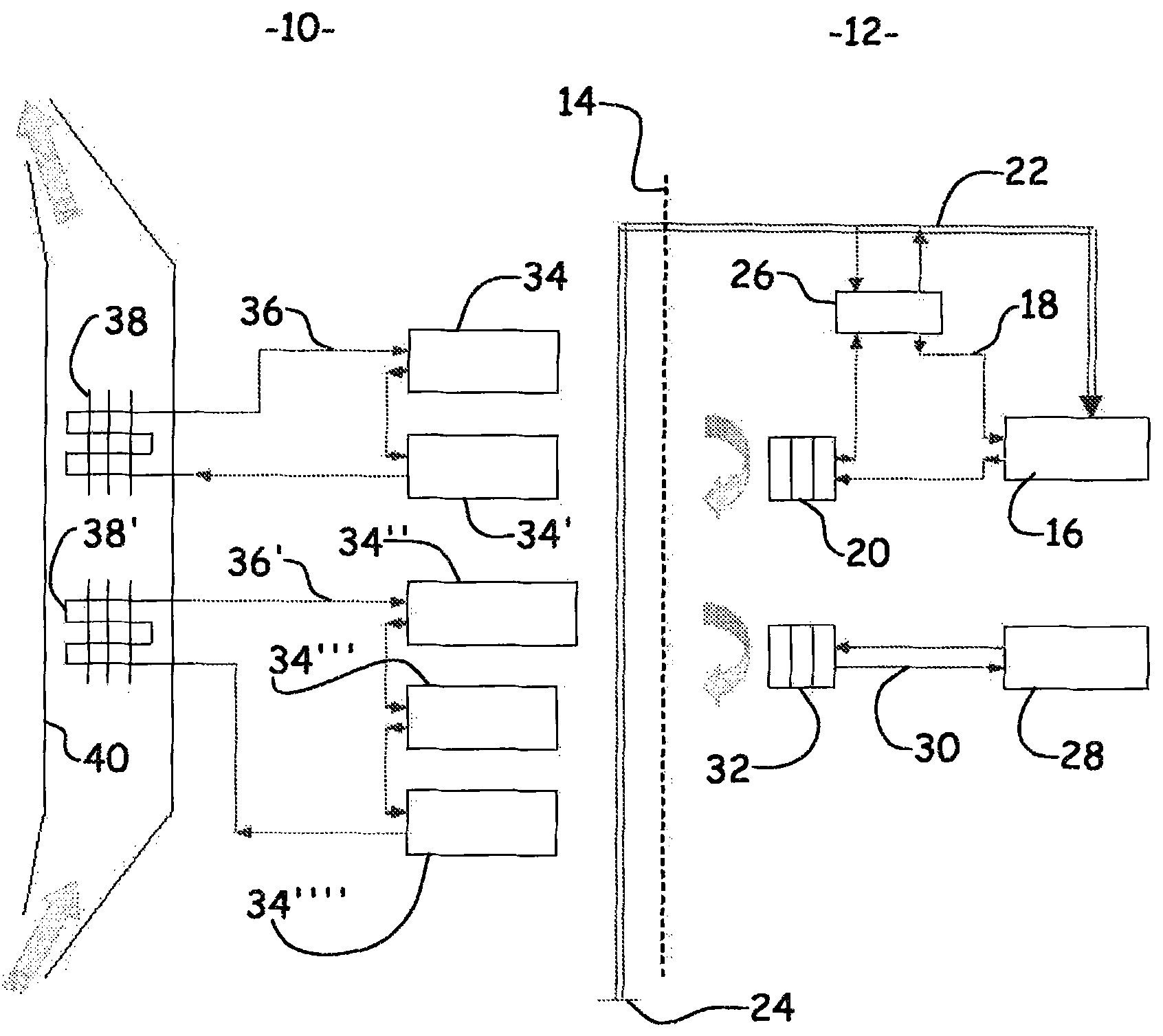
[0031] As mentioned above, an aircraft consists of an airframe and one or several propulsion units.
[0032] The body of an aircraft broadly refers to all parts of the aircraft except the propulsion device, especially the fuselage, side wings, and empennage of the aircraft.
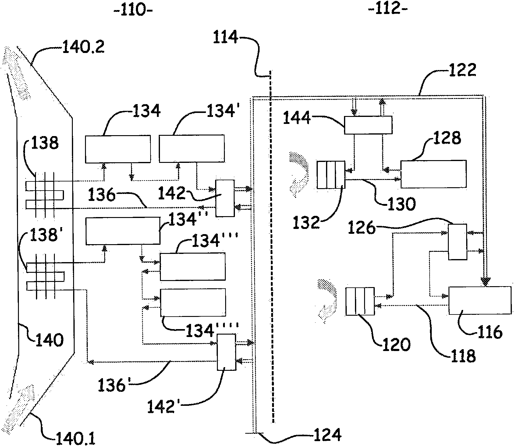
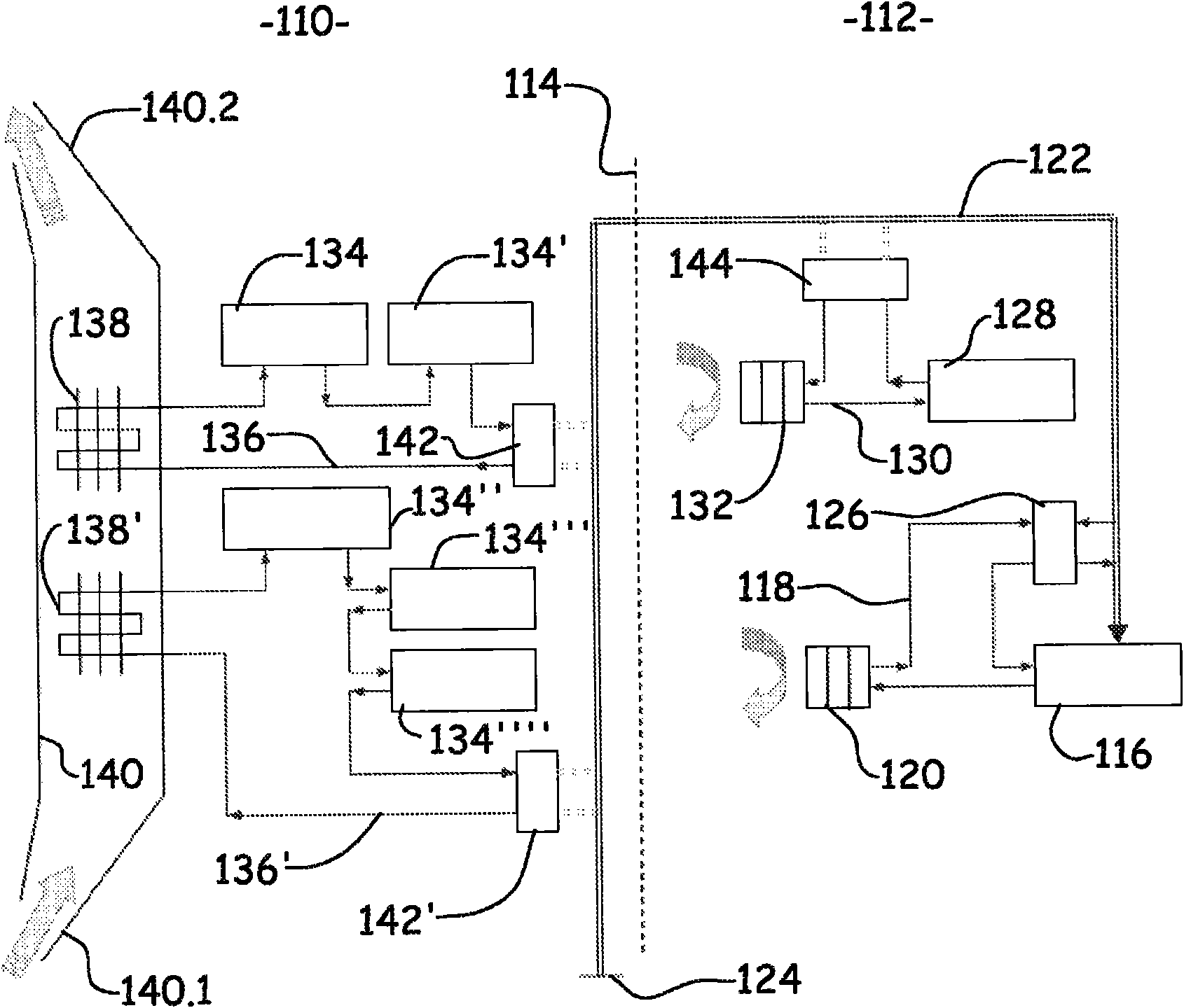
[0033] exist Figures 2 to 6 In , the airframe of the aircraft is schematically indicated by 110 and the propulsion device by 112 . The other propulsion means are not shown and are generally the same.
[0034] In one widely adopted implementation, the propulsion units are generally suspended under the flanks by wing struts. However, the invention is not limited to this implementation and covers all solutions involving the connection between airframe and propulsion means. For the following description, the interface between airframe 110 and propulsion means 112 is indicated by numeral 114 and indicated by dashed lines.
[0035] Parts common to the prior art, used with figure 1 Add 100 to the same nota...
PUM
 Abstract
Description
Claims
Application Information
 - R&D
- Intellectual Property
- Life Sciences
- Materials
- Tech Scout
- Unparalleled Data Quality
- Higher Quality Content
- 60% Fewer Hallucinations
Browse by: Latest US Patents, China's latest patents, Technical Efficacy Thesaurus, Application Domain, Technology Topic, Popular Technical Reports.
© 2025 PatSnap. All rights reserved.Legal|Privacy policy|Modern Slavery Act Transparency Statement|Sitemap|About US| Contact US: help@patsnap.com