Pivotally activated connector components for form-work systems and methods for use of same

A technology of connector and pivoting movement, which is applied to the connection parts of formwork/formwork/working frame, formwork/formwork components, and formwork processing, etc., which can solve the problems of unsanitary conditions of formwork 28

Active Publication Date: 2011-02-09
CFS CONCRETE FORMING SYST
View PDF7 Cites 12 Cited by
  • Summary
  • Abstract
  • Description
  • Claims
  • Application Information

AI Technical Summary

Problems solved by technology

Such leakage may prevent or hinder the use of formwork 28 in applications that require formwork 28 to be impermeable to gases or liquids
Such leakage may also lead to unsanitary conditions on the inside of formwork 28

Method used


Image

  • Pivotally activated connector components for form-work systems and methods for use of same
  • Pivotally activated connector components for form-work systems and methods for use of same
  • Pivotally activated connector components for form-work systems and methods for use of same

Examples


Embodiment Construction

[0041] Specific details are described in the following throughout the description to provide a more thorough understanding to those skilled in the art. However, to avoid unnecessarily obscuring the present disclosure, well-known elements may not be shown or described in detail. Therefore, the description and drawings should be viewed in an illustrative rather than restrictive sense.

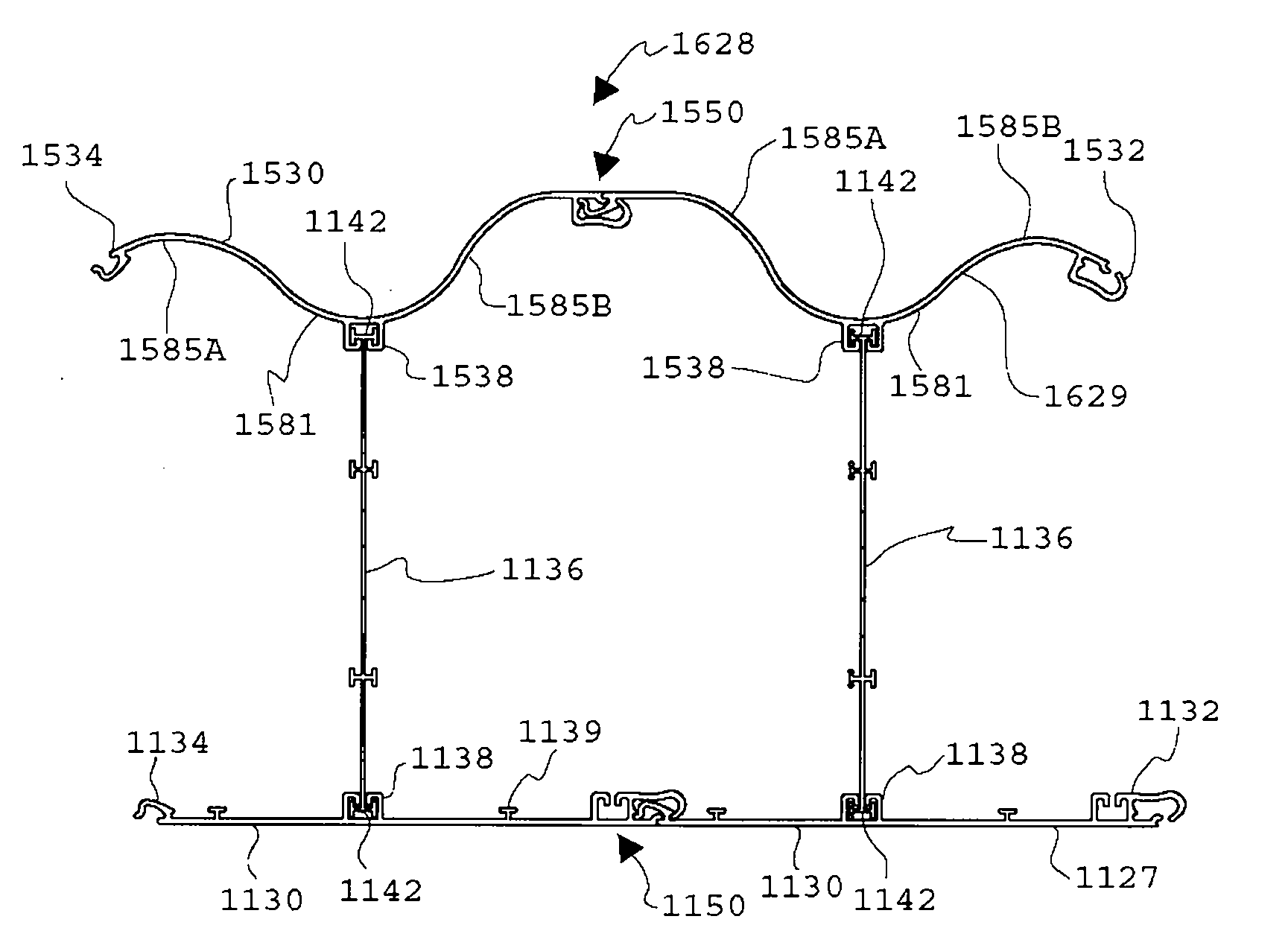
[0042] image 3 It is a partial top view of a modular structural template 128 according to a specific embodiment of the present invention, and the modular structural template 128 is used to make a part of a wall or other structure of a building. image 3 The template 128 of the embodiment includes a wall panel 130 and a support member 136. The components of the template 128 (ie, the panel 130 and the support member 136) are preferably made of a lightweight and elastically deformable material (for example, a suitable plastic) by using an extrusion process. As non-limiting examples, suitable plastics i...


PUM


Abstract

A stay-in-place form for casting concrete structures comprises a plurality of elongate panels interconnectable in edge-to-edge relationship via complementary connector components on their longitudinal edges to define at least a portion of a perimeter of the form. Each panel comprises a first contoured connector component comprising a protrusion on a first longitudinal edge thereof and a second contoured connector component comprising a receptacle on a second longitudinal edge thereof. The panels are connectable to one another in edge-to-edge relationship by positioning the protrusion of a first panel in or near the receptacle of a second panel and effecting relative pivotal motion between the first connector component of the first panel and the second connector component of the second panel to extend the protrusion of the first panel into the receptacle of the second panel.

Description

[0001] References to related applications [0002] The priority claimed in this application is based on: [0003] U.S. Patent Application No. 60 / 986973 entitled "Pivoting movable connector part for modular structure formwork and method of using the pivoting movable connector part" filed on November 9, 2007; and [0004] US Patent Application No. 61 / 022505 entitled "Sliding and pivoting movable connector part for structural formwork system and method of using the sliding and pivoting movable connector part" filed on January 21, 2008. [0005] As far as the United States is concerned, this application requires the following rights under 35U.S.C.§119 or 35U.S.C.§120 (depending on specific circumstances): [0006] U.S. Patent Application No. 60 / 986973, entitled "Pivoting movable connector part for modular structure formwork and method of using the pivoting movable connector part" filed on November 9, 2007, the U.S. patent application This article is hereby incorporated by reference; and the...

Claims


Application Information

Patent Timeline
Patent Type & Authority Applications(China)
IPC IPC(8): E04C2/30E04B2/86E04G17/00E04G19/00
CPCE04B2002/8676E04B2002/867E04B2/8641E04B2/86E04G17/00E04G9/02E04G11/06E04G13/021E04B1/66
Inventor 乔治·大卫·理查森塞米翁·克里武林
Owner CFS CONCRETE FORMING SYST
Why Eureka
Try Eureka