Multi-source spatial power amplifier

A technology for amplifiers and power dividers, applied in the field of semiconductor microwave amplifiers, can solve problems such as unstable risk management difficulties, and achieve the effects of compact structure, reduced distribution loss, and reduced combined loss

Inactive Publication Date: 2011-02-09
THALES TOUR CARPE DIEM PLACE DES COROLLES ESPLANADE NORD COURBEVOIE
View PDF1 Cites 0 Cited by
  • Summary
  • Abstract
  • Description
  • Claims
  • Application Information

AI Technical Summary

Problems solved by technology

[0022] Management of the risk of instability can be difficult as the amplifier is not in a separate cavity;

Method used


Image

  • Multi-source spatial power amplifier
  • Multi-source spatial power amplifier
  • Multi-source spatial power amplifier

Examples


Embodiment Construction

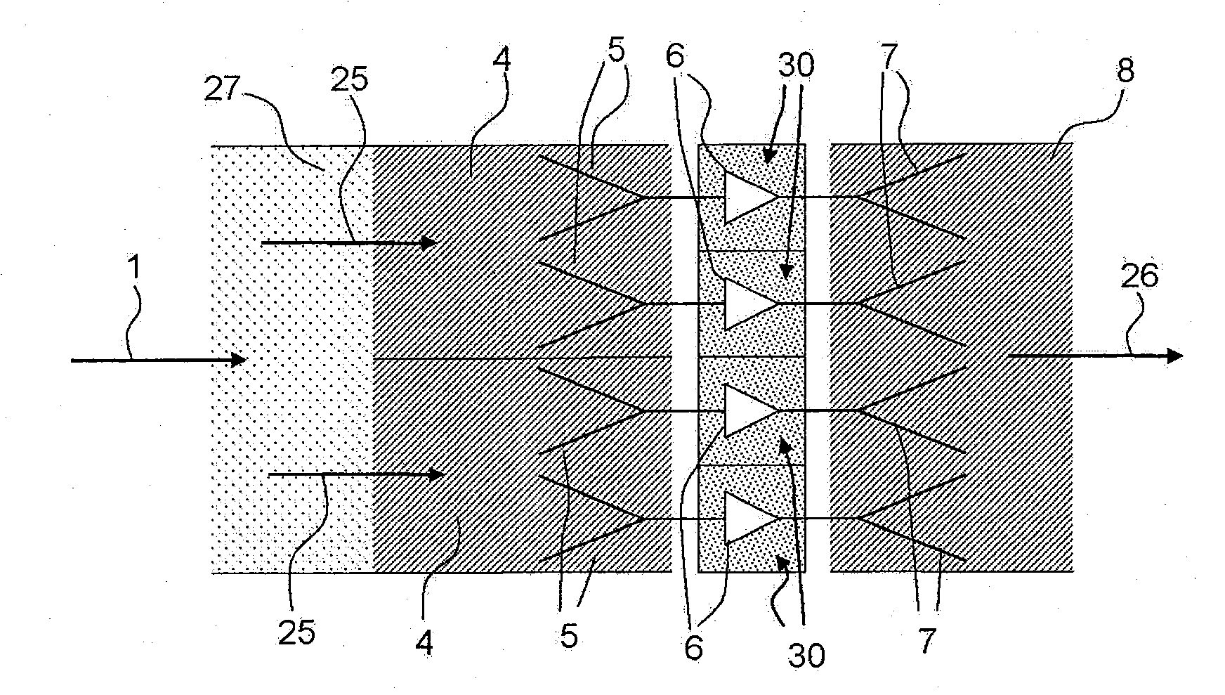
[0071] figure 2 A schematic diagram of an arrangement according to the invention is shown, comprising four combined amplifier modules 30 . The shown arrangement comprises two connecting waveguides 4 preceded by a power splitter 27 . A power splitter 27 is used to split the input microwave signal 1 into two components 25 which are transmitted in the two connecting waveguides 4 . The power divider 27 can be a planar process, or for example a metal waveguide process, such as a "septum divider". This "septum divider" refers to a divider that includes an input end and two rectangular waveguide output ends. Typically in this type of splitter, the two output waveguides are separated at the point of splitting by a thin wall ("septum" in Latin), which can be metallic or resistive.

[0072] In one embodiment, the divider 27 of the planar process is not in the figure 2 The two converters shown in are associated such that the transmission mode of the signal is switched between the pl...


PUM


Abstract

Amplifier combining several amplifying modules and operating in the microwave range, characterized in that it comprises: - a power divider, having one input and at least two outputs, which divides an input microwave signal 1 into several microwave signals 25; connection waveguides 4 enabling the microwave signals 25 delivered by the power divider 27 to propagate; at least one input transition element 5 placed at the output of each connection waveguide 4, enabling the microwave signal 25 to be received; an amplifying module 30 connected to each of the input transitions 5, enabling the signal received by each of the input transitions 5 to be amplified; and an output transition element 7 in planar technology connected to each of the amplifying modules 30, enabling the amplified signals output by the amplifying modules to be combined.

Description

technical field [0001] The present invention relates to the field of semiconductor microwave amplifiers, and more particularly, to power combining systems. Among various combination techniques, the field of the invention relates to spatial power combining systems. Background technique [0002] The reduction of the output power of semiconductor components and the increase of the operating frequency of the amplifying device lead to the need to combine several individual semiconductor amplifiers in order to obtain the output power required for certain applications in the microwave field. [0003] Where many amplifiers are required to achieve the required power levels, radial structures are best suited to meet this need. On the other hand, if a limited number of amplifiers is sufficient, other combination techniques may be more advantageous in terms of implementation, performance, and packaging. [0004] Current power combining systems based on tree-line or waveguide structure...

Claims


Application Information

Patent Timeline
IPC IPC(8): H03F3/60
CPCH03F3/602
Inventor J-P·弗雷斯
Owner THALES TOUR CARPE DIEM PLACE DES COROLLES ESPLANADE NORD COURBEVOIE
Why Eureka
Try Eureka