Improved structure of dispersion disc

A technology of improved structure and dispersing disk, which is applied to mixers with rotating stirring devices, mixers, mixing methods, etc., can solve the problems of low mixing efficiency of dispersing disks, long dispersion time, and differences in shearing action strength, etc., to achieve improved Effect of dispersion efficiency and dispersion effect

Inactive Publication Date: 2011-02-16
SUZHOU SUNMUN TECH CO LTD
View PDF3 Cites 12 Cited by
  • Summary
  • Abstract
  • Description
  • Claims
  • Application Information

AI Technical Summary

Problems solved by technology

However, with the conventional dispersing disc structure, the upper and lower flow fields of the dispersing disc are independent to a certain extent during high-speed stirring, and the liquid material can only be gradually mixed through the upward flow field on the outside, and the shear action intensity of the upper and lower materials on the dispersing disc is strong. have a large difference
For large-volume, multi-component, high-viscosity liquid materials with a mixing volume of more than 10 cubic meters, the mixing efficiency of the dispersing disc with this structure is low, and some components with strong action are easier to concentrate in local areas and mix evenly Requires stronger shear action, takes longer to disperse

Method used


Image

  • Improved structure of dispersion disc
  • Improved structure of dispersion disc

Examples


Embodiment 1

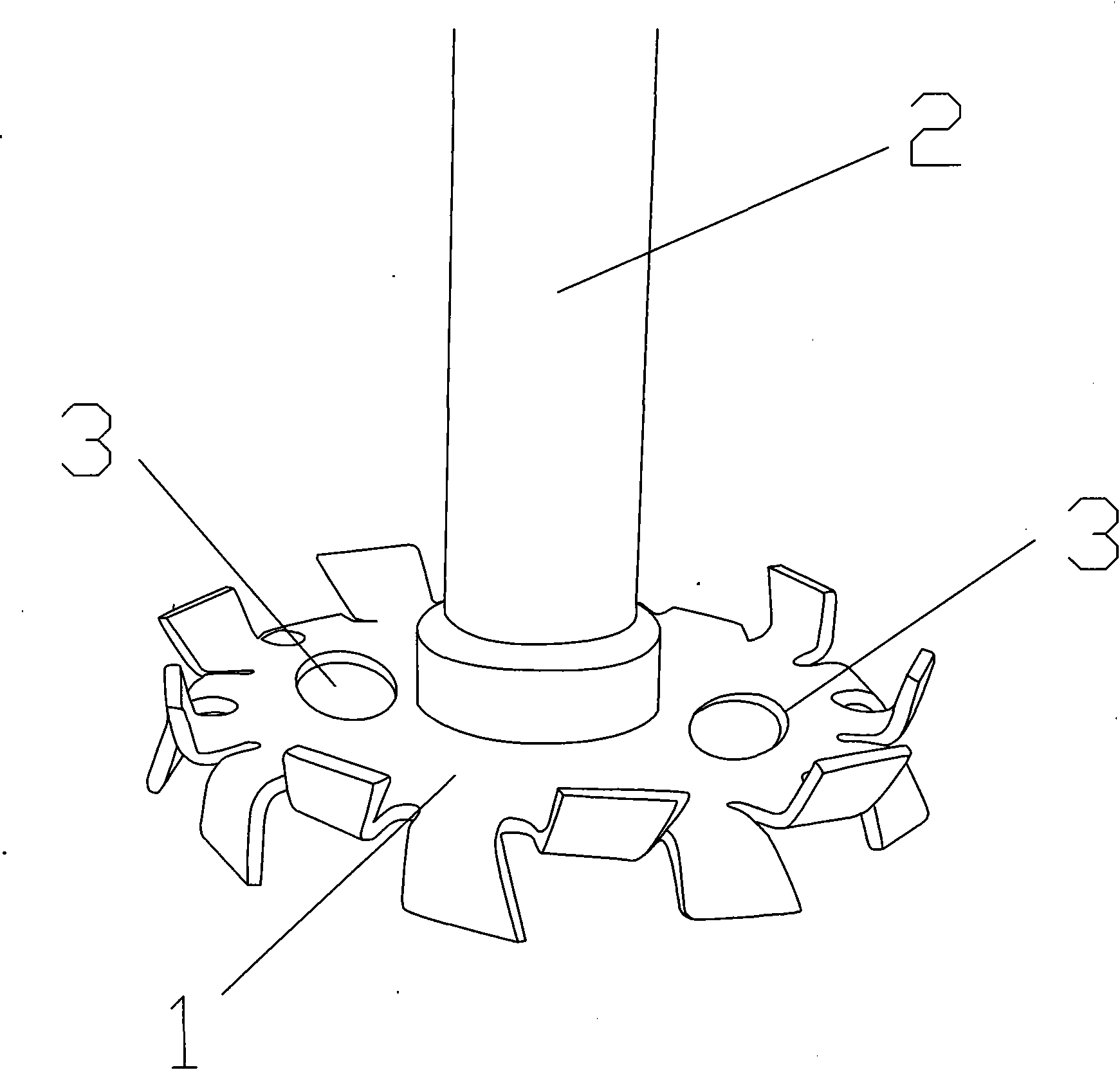
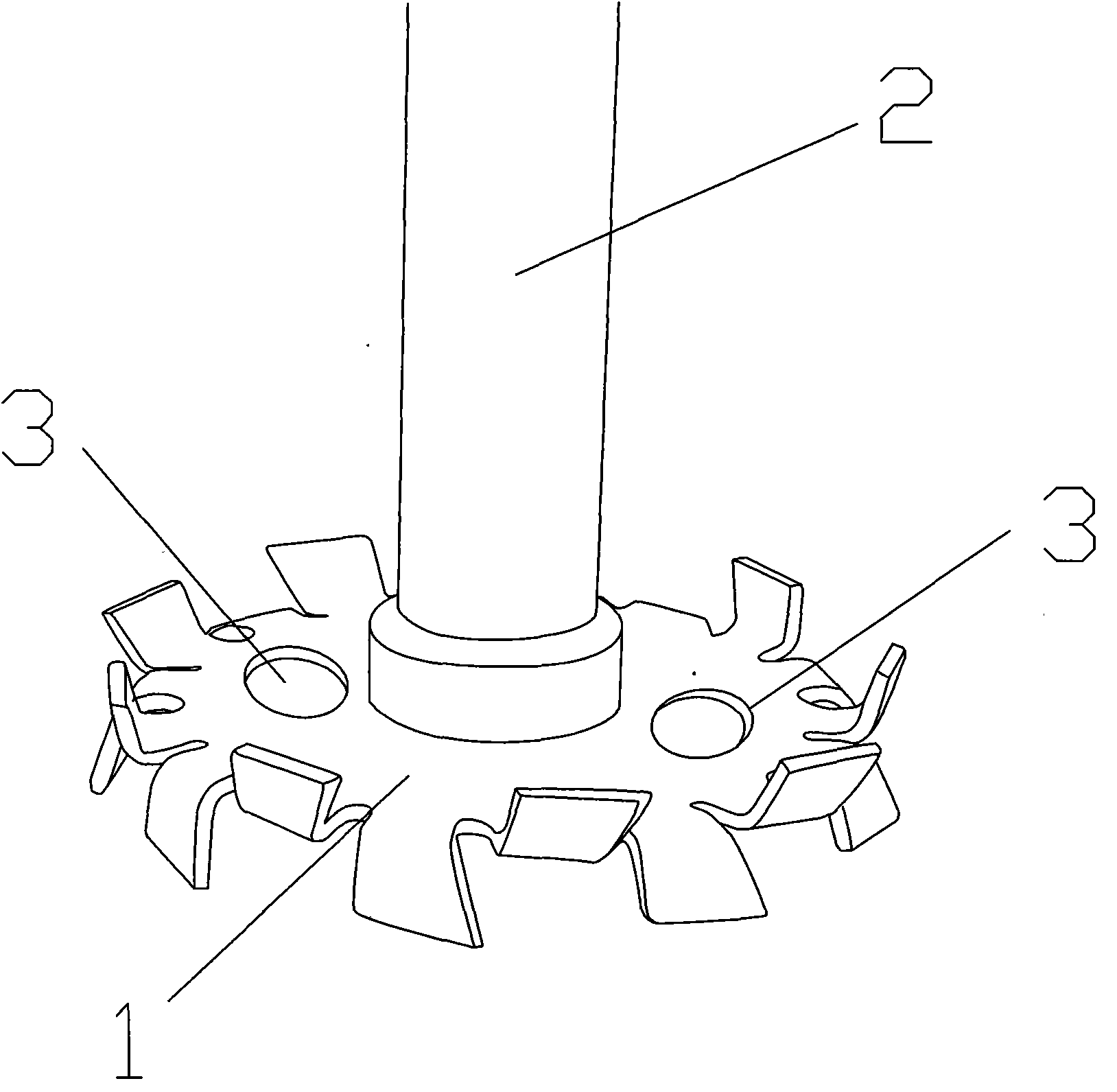
[0011] An improved structure of a dispersing disc, one end of the stirring shaft 2 is fixedly connected to the center of the dispersing disc 1, and a pair of circular holes 3 are arranged symmetrically on the surface of the dispersing disc 1 opposite to the center of the dispersing disc and away from the stirring shaft. The radii of the shaped holes 3 are both 1 / 2 of the radius of the dispersing disk, and the centers of the pair of circular holes 3 are all located at 1 / 2 of the radius of the dispersing disk.

Embodiment 2

[0013] An improved structure of a dispersing disc, one end of the stirring shaft 2 is fixedly connected to the center of the dispersing disc 1, and two pairs of circular holes 3 are symmetrically arranged on the surface of the dispersing disc 1 opposite to the center of the dispersing disc and away from the stirring shaft. The radii of the pair of circular holes 3 are both 1 / 3 of the radius of the dispersing disk, and the centers of the two pairs of circular holes 3 are located at 1 / 2 of the radius of the dispersing disk.

Embodiment 3

[0015] An improved structure of a dispersing disc, one end of the stirring shaft 2 is fixedly connected to the center of the dispersing disc 1, and three pairs of circular holes 3 are symmetrically arranged on the surface of the dispersing disc 1 opposite to the center of the dispersing disc and away from the stirring shaft. The radii of the circular holes 3 are all 1 / 4 of the radius of the dispersing disk, and the centers of the three pairs of circular holes 3 are all located at 1 / 2 of the radius of the dispersing disk.


PUM


Abstract

The invention discloses an improved structure of a dispersion disc. A plurality of pairs of circular holes are regularly arranged on the dispersion disc, and each pair of circular holes are respectively and symmetrically distributed relative to a stirring shaft on the dispersion disc. Thus, an upper flow field and a lower flow field on the dispersion disc can form a continuous circulating flow field. When a material is stirred at a high speed, the material can be rapidly and uniformly mixed, and the dispersion efficiency and the dispersion effect of the material can be greatly increased. The improved dispersion disc is especially applicable to the preparation of large-scale high-viscosity liquid materials with uniform properties and large mixed volume more than 10 cubic meters.

Description

technical field [0001] The invention relates to an improved structure of a dispersing disc, in particular to a dispersing disc structure for pre-dispersing large-volume, multi-component and high-viscosity liquid materials with a mixing volume greater than 10 cubic meters. Background technique [0002] High-speed disperser is a pre-dispersion equipment for high-viscosity pigment dispersion. The traditional high-speed disperser uses a high-hardness metal disc to form a high-speed shear flow field in the high-viscosity liquid material, which can pulverize the pigment powder to the micron level and promote the wetting of the pigment surface. However, with the conventional dispersing disc structure, the upper and lower flow fields of the dispersing disc are independent to a certain extent during high-speed stirring, and the liquid material can only be gradually mixed through the upward flow field on the outside, and the shear action intensity of the upper and lower materials on t...

Claims


Application Information

Patent Timeline
IPC IPC(8): B01F15/00B01F7/26B01F3/10B01F27/93B01F23/47
Inventor 许丹杜长森孙贵生
Owner SUZHOU SUNMUN TECH CO LTD
Why Eureka
Try Eureka